In Stock Hot Product
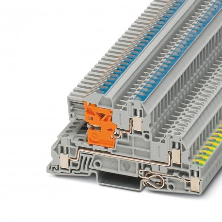
UTI 2,5-PE/L/NT
UTI 2,5-PE/L/NT 3076028 PHOENIX CONTACT Installation ground terminal block, Screw connection, Cross section:..
$0.00USD
4021 in stock
Key Specifications
:6 kV
Note:Assembly instructions:For secure fastening of the neutral busbar, supports must be set at the beginning and end of each terminal strip as well as every 20 cm on longer terminal strips.
Color:gray
Width:5.2 mm
Supplier Information
Products: 0
Usually ships within 2-3 business days
Quality Guaranteed
Fast Shipping
Technical Support
Technical Specifications
| Parameter | Value |
|---|---|
| 6 kV | |
| Note | Assembly instructions:For secure fastening of the neutral busbar, supports must be set at the beginning and end of each terminal strip as well as every 20 cm on longer terminal strips. |
| Color | gray |
| Width | 5.2 mm |
| Height | 51.20 mm |
| Length | 93.5 mm |
| Setpoint | 1 N |
| ASD level | 6.12 (m/s2)2/Hz |
| Shock form | Half-sine |
| Acceleration | 3.12 g |
| Screw thread | M3 |
| Test spectrum | Service life test category 2, bogie mounted |
| Shock duration | 18 ms |
| Test frequency | f1= 5 Hz to f2= 250 Hz |
| End cover width | 2.2 mm |
| Height NS 35/15 | 59 mm |
| Open side panel | ja |
| Test directions | X-, Y- and Z-axis |
| Height NS 35/7,5 | 51.5 mm |
| Number of levels | 3 |
| Pollution degree | 3 |
| Stripping length | 9 mm |
| Connection method | Screw connection |
| Finger protection | guaranteed |
| Shock test result | Test passed |
| Bending test turns | 135 |
| Nominal current IN | 24 A (with 4 mm² conductor cross section) |
| Nominal voltage UN | 400 V (phase conductor/phase conductor) |
| Short-time current | 0.3 kA |
| Insulating material | PA |
| Rated surge voltage | 4 kV |
| Tensile test result | Test passed |
| Maximum load current | 30 A (with 4 mm² conductor cross section and 3-pos. terminal block) |
| Overvoltage category | III |
| Result of aging test | Test passed |
| Tight fit on carrier | NS 35 |
| Nominal cross section | 4 mm² |
| Number of connections | 5 |
| Tightening torque max | 0.6 Nm |
| Result of bending test | Test passed |
| Result of thermal test | Test passed |
| Test duration per axis | 5 h |
| Tightening torque, min | 0.5 Nm |
| Tractive force setpoint | 10 N |
| Insulating material group | I |
| Internal cylindrical gage | A3 |
| Requirements, voltage drop | ≤ 3.2 mV |
| Back of the hand protection | guaranteed |
| Bending test rotation speed | 10 rpm |
| Result of voltage-drop test | Test passed |
| Surge voltage test setpoint | 7.3 kV |
| Result of surge voltage test | Test passed |
| Number of shocks per direction | 3 |
| Result of tight fit on support | Test passed |
| Short circuit stability result | Test passed |
| Test specification, shock test | DIN EN 50155 (VDE 0115-200):2008-03 |
| Result of temperature-rise test | Test passed |
| Conductor cross section AWG max. | 12 |
| Conductor cross section AWG min. | 24 |
| Conductor cross section solid max. | 4 mm² |
| Conductor cross section solid min. | 0.2 mm² |
| Shock protection test specification | DIN EN 50274 (VDE 0660-514):2002-11 |
| Conductor cross section tensile test | 0.2 mm² |
| Conductor cross section flexible max. | 4 mm² |
| Conductor cross section flexible min. | 0.2 mm² |
| Flammability rating according to UL 94 | V0 |
| Oscillation, broadband noise test result | Test passed |
| Max. AWG conductor cross section, flexible | 12 |
| Min. AWG conductor cross section, flexible | 24 |
| Power frequency withstand voltage setpoint | 1.89 kV |
| Bending test conductor cross section/weight | 0.2 mm² / 0.2 kg |
| Conductor cross section short circuit testing | 2.5 mm² |
| Static insulating material application in cold | -60 °C |
| 2 conductors with same cross section, solid max. | 1.5 mm² |
| 2 conductors with same cross section, solid min. | 0.2 mm² |
| Result of power-frequency withstand voltage test | Test passed |
| Test specification, oscillation, broadband noise | DIN EN 50155 (VDE 0115-200):2008-03 |
| 2 conductors with same cross section, stranded max. | 1.5 mm² |
| 2 conductors with same cross section, stranded min. | 0.2 mm² |
| Relative insulation material temperature index (Elec., UL 746 B) | 130 °C |
| Proof of thermal characteristics (needle flame) effective duration | 30 s |
| Ageing test for screwless modular terminal block temperature cycles | 192 |
| Conductor cross section flexible, with ferrule with plastic sleeve max. | 2.5 mm² |
| Conductor cross section flexible, with ferrule with plastic sleeve min. | 0.25 mm² |
| Temperature index of insulation material (DIN EN 60216-1 (VDE 0304-21)) | 130 °C |
| Conductor cross section flexible, with ferrule without plastic sleeve max. | 2.5 mm² |
| Conductor cross section flexible, with ferrule without plastic sleeve min. | 0.25 mm² |
| 2 conductors with same cross section, stranded, ferrules without plastic sleeve, max. | 0.75 mm² |
| 2 conductors with same cross section, stranded, ferrules without plastic sleeve, min. | 0.25 mm² |
| 2 conductors with same cross section, stranded, TWIN ferrules with plastic sleeve, max. | 0.75 mm² |
| 2 conductors with same cross section, stranded, TWIN ferrules with plastic sleeve, min. | 0.5 mm² |
| Result of the test for mechanical stability of terminal points (5 x conductor connection) | Test passed |
Product Description
Ground terminal for distribution, Note on assembly: To securely fix the neutral busbar, trestles must be placed at the beginning and end of each terminal strip, as well as longer strips every 20cm., n
Key Features
- Industrial grade quality
- RoHS compliant
- CE certified
- 1-year warranty
Product Documents
Datasheet
Technical specifications and performance data
User Manual
Installation and operation guide


