In Stock Hot Product
USFC21
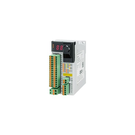
USFC21 SF-C21 PANASONIC Safety control unit for safety light curtain and other safety products, 8 inputs 24V..
$0.00USD
4642 in stock
Key Specifications
Item:Specifications
Weight:Net weight: 190 g approx.Gross weight: 320 g approx.
Product:Safety Control Unit
Material:Main unit enclosure: Polycarbonate / ABS polymer alloyEnclosure: Polycarbonate
Supplier Information
PANASONIC
Products: 4316
Usually ships within 2-3 business days
Quality Guaranteed
Fast Shipping
Technical Support
Technical Specifications
| Parameter | Value |
|---|---|
| Item | Specifications |
| Weight | Net weight: 190 g approx.Gross weight: 320 g approx. |
| Product | Safety Control Unit |
| Material | Main unit enclosure: Polycarbonate / ABS polymer alloyEnclosure: Polycarbonate |
| PFHD/ MTTFD | 9.73 x 10⁻¹⁰/ 100 years or more |
| Part Number | SF-C21 |
| Cable length | 100 m328.084 ftor less |
| Product name | Safety Control Unit SF-C21 |
| Product Number | SF-C21 |
| Pollution degree | 2 |
| Connecting method | Input / output and power supply: Detachable spring cage termina l blocksRS-485: Detachable spring-cage terminal blockUSB: Mini-B male |
| Related standards | IEC 60947-1, IEC 60947-5-1, IEC 60947-5-2, IEC 60947-5-5, IEC 60947-5-8, IEC 61496-1, IEC TS 62046, ISO 13851 |
| Interlock function | Incorporated |
| Operating altitude | 2,000 m6561.680 ftor less(Note) Do not use or store this device in a pressurized environment beyond the atmospheric pressure at sea level. |
| Vibration resistance | 5 to 8.4 Hz frequency, 3.5 mm0.138 inhalf amplitude, 8.4 to 150 Hz frequency, Max. acceleration 9.8 m/s2(1 G), in X, Y and Z directions for two hours each (IEC / EN 60068-2-6) |
| Logic setting function | Input mode, control mode, output mode, reset mode, auxiliary ou tput mode |
| Excess voltage category | II |
| Muting indicator output | Semiconductor photo MOS relay output x 1- Maximum load current: 60 mA- Supply voltage: Same as the voltage of the power supply for internal- Residual voltage: 2.5 V or less- Leakage current: 100 μA or less (Including power supply OFF condition) |
| Lockout release function | Incorporated |
| Logic selection function | No.0: Customization controlNo.1: Overall stop controlNo.2: Parallel muting controlNo.3: Sequential muting controlNo.4: Partial stop control 1No.5: Partial stop control 2No.6: Two-hand controlNo.7: OR controlNo.8: Operation mode selection control |
| Safety input (IN1 to IN8) | 2 inputs x 4, Rated voltage: Same as the voltage of the power supply for internal |
| Applicable standards : EMC | IEC 61000-6-2, IEC 61326-3-1, EN 55011 |
| Startup time after power on | 2 sec. or less |
| Applicable standards : Safety | IEC 61508-1 to 3, EN 61508-1 to 3 (SIL3), ISO 13849-1:2015 (Category 4, PLe), IEC 61131-2, IEC 61010-2-201, IEC 62061 (SILCL3), UL 61010-1, UL 61010-2-201, UL 1998 |
| Control output (OUT1 to OUT4) | PNP open-collector transistor with 2 outputs x 2- Maximum source current: 300 mA / output- Applied voltage: Same as the voltage of the power supply for external- Residual voltage: 2.5 V or less- Leakage current: 100 μA or less (Including power supply OFF condition) |
| Communication function (MODBUS RTU) | Interface: RS-485Protocol: MODBUS RTUMaximum transmission distance: 100 m328.084 ftMaximum number of units that can be connected: 8 units (slaves) |
| External device monitoring function | Incorporated |
| Safety input (IN1 to IN8) : ON level | Input voltage: 18 VInput current: 3.5 mA |
| Muting indicator output : Output mode | ON when muting / override |
| Safety input (IN1 to IN8) : OFF level | Input voltage: 5 VInput current: 1.0 mA |
| Muting indicator output : Response time | 10 ms or less |
| Applicable regulations and certifications | CE Marking (Machinery Directive, EMC Directive, RoHS Directive), UKCA Marking [Supply of Machinery (Safety)Regulations, EMC Regulations, RoHS Regulations], TÜV SÜD certification, Korea's Radio Waves Act conformity registration |
| Environmental resistance:Ambient humidity | 30 to 85 % RH, Storage: 30 to 85 % RH |
| Environmental resistance:Shock resistance | 147 m/s2(15 G) 11 ms in X, Y and Z directions for three times each (IEC / EN 60068-2-27) |
| Supply voltage : Power supply for external | 24 V DC+10-15% Ripple P-P10 % or less(Note) "Power supply for external" is the power supply for control output / auxiliary output. The power supplies for internal and external are insulated.(Note) The power supply unit connected to this device must satisfy the conditions below.- Output voltage within 20.4 V to 26.4 V DC (Ripple P-P: 10 % or less.)- Power supply unit SELV (safety extra low voltage) / PELV (protected extra low voltage) conforming to the EMC Directive and Low-voltage Directive (In case CE Marking conformity is required.)- Power supply unit conforming to the Low-voltage Directive and with an output of 100 VA or less- Power supply unit SELV (safety extra low voltage) / PELV (protected extra low voltage) conforming to the EMC Regulations and Low-voltage Regulations (In case UKCA Marking conformity is required.)- Power supply unit with an output holding time of 20 ms or more.- Power supply unit corresponding to CLASS 2 (In case C-TÜV US Listing Mark conformity is required.) |
| Supply voltage : Power supply for internal | 24 V DC+10-15% Ripple P-P10 % or less(Note) "Power supply for internal" is the power supply for safety input. The power supplies for internal and external are insulated.(Note) The power supply unit connected to this device must satisfy the conditions below.- Output voltage within 20.4 V to 26.4 V DC (Ripple P-P: 10 % or less.)- Power supply unit SELV (safety extra low voltage) / PELV (protected extra low voltage) conforming to the EMC Directive and Low-voltage Directive (In case CE Marking conformity is required.)- Power supply unit conforming to the Low-voltage Directive and with an output of 100 VA or less- Power supply unit SELV (safety extra low voltage) / PELV (protected extra low voltage) conforming to the EMC Regulations and Low-voltage Regulations (In case UKCA Marking conformity is required.)- Power supply unit with an output holding time of 20 ms or more.- Power supply unit corresponding to CLASS 2 (In case C-TÜV US Listing Mark conformity is required.) |
| Control output (OUT1 to OUT4) : Output mode | True: ONFalse: OFF |
| Safety input (IN1 to IN8) : Input impedance | 4.7 KΩ approx. |
| Environmental resistance:Ambient temperature | -10 to +55 ℃+14 to +131 ℉(No dew condensation or icing allowed), Storage: -25 to +60 ℃-13 to +140 ℉ |
| Control output (OUT1 to OUT4) : Response time | OFF response: 10 ms or lessON response: 100 ms or less |
| Environmental resistance:Degree of protection | IP20 (IEC)(must be installed in a control panel with protectio n IP54 or higher) |
| Environmental resistance:Insulation resistance | 20 MΩ, or more, with 500 V DC megger(All inputs connected together - USB port, all inputs connected together - RS-485 port, USB port - RS-485 port, between all supply terminals connected together and enclosure, all outputs connected together - all input connected together, all outputs connected together - USB port, all outputs connected together - RS-485 port) |
| Current consumption : Power supply for external | 100 mA or less(Note) "Power supply for external" is the power supply for control output / auxiliary output. The power supplies for internal and external are insulated.(Note) The power supply unit connected to this device must satisfy the conditions below.- Output voltage within 20.4 V to 26.4 V DC (Ripple P-P: 10 % or less.)- Power supply unit SELV (safety extra low voltage) / PELV (protected extra low voltage) conforming to the EMC Directive and Low-voltage Directive (In case CE Marking conformity is required.)- Power supply unit conforming to the Low-voltage Directive and with an output of 100 VA or less- Power supply unit SELV (safety extra low voltage) / PELV (protected extra low voltage) conforming to the EMC Regulations and Low-voltage Regulations (In case UKCA Marking conformity is required.)- Power supply unit with an output holding time of 20 ms or more.- Power supply unit corresponding to CLASS 2 (In case C-TÜV US Listing Mark conformity is required.) |
| Current consumption : Power supply for internal | 200 mA or less(Note) "Power supply for internal" is the power supply for safety input. The power supplies for internal and external are insulated.(Note) The power supply unit connected to this device must satisfy the conditions below.- Output voltage within 20.4 V to 26.4 V DC (Ripple P-P: 10 % or less.)- Power supply unit SELV (safety extra low voltage) / PELV (protected extra low voltage) conforming to the EMC Directive and Low-voltage Directive (In case CE Marking conformity is required.)- Power supply unit conforming to the Low-voltage Directive and with an output of 100 VA or less- Power supply unit SELV (safety extra low voltage) / PELV (protected extra low voltage) conforming to the EMC Regulations and Low-voltage Regulations (In case UKCA Marking conformity is required.)- Power supply unit with an output holding time of 20 ms or more.- Power supply unit corresponding to CLASS 2 (In case C-TÜV US Listing Mark conformity is required.) |
| Safety input (IN1 to IN8) : Rated input current | 5 mA approx. |
| Auxiliary output(AUX1 to AUX4)(Non-safety output) | PNP open-collector transistor with 1 output x 4- Maximum source current: 60 mA / output- Applied voltage: Same as the voltage of the power supply for external- Residual voltage: 2.5 V or less- Leakage current: 100 μA or less (Including power supply OFF condition) |
| Control output (OUT1 to OUT4) : ON delay function | Incorporated |
| Environmental resistance:Voltage withstandability | 1,000 V AC for one min.(All inputs connected together - USB port, all inputs connected together - RS-485 port, USB port - RS-485 port, between all supply terminals connected together and enclosure, all outputs connected together - all input connected together, all outputs connected together - USB port, all outputs connected together - RS-485 port) |
| Control output (OUT1 to OUT4) : OFF delayfu nction | Incorporated |
| Muting indicator output : Short-circuit protection | Incorporated |
| Control output (OUT1 to OUT4) : Short-circuit protection | Incorporated |
| Safety input (IN1 to IN8) : Duration of detectable ON state | 10 ms or more |
| Safety input (IN1 to IN8) : Duration of undetectable OFF state | 0.7 ms or less |
| Auxiliary output(AUX1 to AUX4)(Non-safety output) : Response time | 10 ms or less |
| Auxiliary output(AUX1 to AUX4)(Non-safety output) : Short-circuit protection | Incorporated |
| Auxiliary output(AUX1 to AUX4)(Non-safety output) : Output mode (Factory defaults) | AUX1: Negative logic of OUT1 / OUT2 (ON when OUT1 / OUT2 is OFF)AUX2: Negative logic of OUT3 / OUT4 (ON when OUT3 / OUT4 is OFF)AUX3: Reset trigger output (ON under reset release wait condition)AUX4: Lockout output (OFF when lockout) |
| Auxiliary output(AUX1 to AUX4)(Non-safety output) : Output mode (Any of the auxiliary outputs can be customized using the software tool) | Negative logic of OUT1 / OUT2 (ON when OUT1 / OUT2 is OFF)Negative logic of OUT3 / OUT4 (ON when OUT3 / OUT4 is OFF)Positive logic of OUT1 / OUT2 (ON when OUT1 / OUT2 is ON)Positive logic of OUT3 / OUT4 (ON when OUT3 / OUT4 is ON)Outputs A, B, C, and D of diagnosis results of input blocks (ON when logic is true)Outputs E, F, and G of internal logic circuit diagnostic results (ON when logic is true)Reset trigger output (ON under reset release wait condition)Lockout output (OFF when lockout)Muting indicator output (ON when muting / override)Monitor output in response to IN1 to IN8 (ON when input)No output (normally OFF) |
Product Description
Control unit for barriers and other safety products, Cat. 4(Ple) and SIL3, 4 inputs, 2 outputs, 8 pre-established logics according to cat regulations. 4 (Ple) and 1 customizable logic, self-diagnostic
Key Features
- Industrial grade quality
- RoHS compliant
- CE certified
- 1-year warranty
Product Documents
Datasheet
Technical specifications and performance data
User Manual
Installation and operation guide


