In Stock Hot Product
USF4DH80
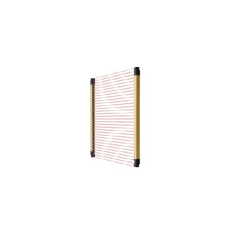
USF4DH80 SF4D-H80 PANASONIC Safety light curtain type 4, version 2, hand protection 1590mm, PNP/NPN, connect..
$0.00USD
3619 in stock
Key Specifications
Item:Specifications
PFHD:3.69×10⁻⁹
MTTFD:318 years or more
Remark:Where measurement conditions have not been specified precisely, the conditions used were an ambient temperature of +20 ℃+68 ℉.PFHD: Probability of Dangerous Failure per Hour, MTTFD: Mean Time to Dangerous Failure (in years).
Supplier Information
PANASONIC
Products: 4316
Usually ships within 2-3 business days
Quality Guaranteed
Fast Shipping
Technical Support
Technical Specifications
| Parameter | Value |
|---|---|
| Item | Specifications |
| PFHD | 3.69×10⁻⁹ |
| MTTFD | 318 years or more |
| Remark | Where measurement conditions have not been specified precisely, the conditions used were an ambient temperature of +20 ℃+68 ℉.PFHD: Probability of Dangerous Failure per Hour, MTTFD: Mean Time to Dangerous Failure (in years). |
| Details | Min. sensing object ø25 mmø0.984 in(20 mm0.787 inbeam pitch) |
| Product | Safety Light Curtain [Type 4 PLe SIL3] |
| Material | Enclosure : Aluminum, Detection surface : Polycarbonate resin and stainless steel (SUS304), Upper cap / lower cap : Nylon |
| Accessories | SF4B-TR25 (test rod) : 1 pc. |
| Part Number | SF4D-H80 |
| Product name | Compact & Robust Safety Light Curtain [Type 4 PLe SIL3] SF4D |
| Safety state | Control output (OSSD 1 / 2) OFF state |
| Power voltage | 24 V DC+20-30 %Ripple P-P 10 % or less (excluding voltage drop due to cable)(Note): In consideration of the voltage drop caused by the cable, use Control output (OSSD 1, OSSD 2) source / sink current and cable length as a guideline. |
| Product Number | SF4D-H80 |
| Subsystem type | Type B (IEC 61508-2) |
| Cable extension | Total length of emitter / receiver can be extended up to 70 m229.659 fteach using optional mating cable (including the lengthof series mating cables)(Note): In consideration of the voltage drop caused by the cable, use Control output (OSSD 1, OSSD 2) source / sink current and cable length as a guideline. |
| Muting function | Incorporated (12-core cable) |
| Operating range | Short mode : 0.2 to 9 m0.656 to 29.528 ftLong mode : 0.8 to 15 m2.625 to 49.213 ft(selectable by DIP switch)(Note): The operating range is the possible setting distance between the emitter and the receiver. |
| Emitting element | Infrared LED (peak emission wavelength : 850 nm0.0335 mil) |
| Pollution degree | 3 |
| Connecting method | By connector |
| Override function | Incorporated (12-core cable) |
| Protective height | 1,590 mm62.598 in(Note): When using as a safety device for a press machine in China, the length from the center of the first beam channel to the center of the last beam channel become to be protective height. |
| Interlock function | Incorporated [Manual reset / auto reset (selectable by wiring)] (8-core cable or 12-core cable) |
| Operating altitude | 2,000 m6,561.68 ftor less(Note): Do not use or store in an environment pressurized to atmospheric pressure or higher at an altitude of 0 m. |
| Optional functions | Fixed blanking function, floating blanking function, interlock setting function, external device monitoring setting function, auxiliary output settingfunction, application indicator setting function, muting setting function, override setting function, protect function, cable switching function(Note): To use optional functions, the SF4D-TM1 (optional) and Configurator Light Curtain setting software are required. |
| Ambient illuminance | Incandescent light : 5,000 ℓx or less at the light-receiving surface |
| Current consumption | Emitter : 120 mA or lessReceiver : 150 mA or less |
| Min. sensing object | ø25 mmø0.984 inopaque object(Note): When the floating blanking function is used, the size of the minimum sensing object varies. For the detail, refer to the section on Safety distance. |
| Power save function | Incorporated |
| Test input function | Incorporated |
| No. of beam channels | 80 |
| Failure response time | Within response time (OFF response) |
| Synchronization method | Line synchronization / optical synchronization (selectable by DIP switch) |
| Effective aperture angle | ±2.5° or less at a sensing range of 3 m9.843 ftor longer (based on IEC 61496-2) |
| Lockout release function | Incorporated |
| T1 (proof test interval) | 20 years |
| Applicable standards:China | GB/T 4584 |
| Applicable standards:Japan | JIS B 9704-1/2 (Type 4), JIS B 9705-1 (Category 4), JIS C 0508-1 to 3 (SIL3) |
| Applicable standards:Europe | EN ISO 13849-1:2015 (Category 4, PLe), EN 55011, EN 61000-6-2, EN IEC 63000 |
| SFF (Safe Failure Fraction) | 99% |
| Application indicator function | Incorporated (only the receiver lights up when optical synchronization is used) |
| HFT (Hardware Fault Tolerance) | 1 |
| Control outputs (OSSD 1, OSSD 2) | PNP open-collector transistor / NPN open collector transistor (selectable)<PNP output selected>・Maximum source current : 350 mA・Applied voltage : Same as supply voltage(between control output and +V)・Residual voltage : 2 V or less (source current 350 mA)(excluding voltage drop due to cable)・Leakage current : 0.2 mA or less (including power OFF state)・Maximum load capacity : 2.2 μF・Load wiring resistance : 3 Ω or less<NPN output selected>・Maximum sink current : 350 mA・Applied voltage : Same as supply voltage(between control output and 0 V)・Residual voltage : 2 V or less (sink current 350 mA)(excluding voltage drop due to cable)・Leakage current : 0.2 mA or less (including power OFF state)・Maximum load capacity : 2.2 μF・Load wiring resistance : 3 Ω or less |
| Interference prevention function | <Not connected in series/parallel>・Line synchronization : 2 units or less (auto)・Optical synchronization : 2 units or less (selectable by DIP switch)<Connected in series/parallel>・Series connection : 5 units or less (total number of beam channels 256 or less)・Parallel connection : 3 units or less (total number of beam channels 192 or less)(Note)・Series / parallel connection mixed : 5 units or less (total number of beam channels 144 or less)(Note)(Note): The setting can be changed when the SF4D-TM1 (optional) and Configurator Light Curtain setting software are used. |
| Applicable standards:North America | ANSI/UL 61496-1/2 (Type 4),CAN/CSA C22.2 No.14, CAN/CSA E61496-1/2 |
| External device monitoring function | Incorporated (8-core cable or 12-core cable) |
| Weight(Total of emitter and receiver) | 4,000g approx. |
| Applicable regulations and certifications | CE Marking (Machinery Directive, EMC Directive, RoHS Directive) , UKCA Marking (Machinery Regulations, EMC Regulations, RoHS Regulations), TÜV SÜD certification (U.S.A., Canada), OSHA 1910.212, OSHA 1910.217(C), ANSI B11.1 to B11.19, ANSI/RIA 15.06, Korea KCs mark |
| Auxiliary output (AUX)(Non-safety output) | PNP open-collector transistor / NPN open collector transistor (selectable)<PNP output selected>・Maximum source current : 60 mA・Applied voltage : Same as supply voltage(between auxiliary output and +V)・Residual voltage : 2 V or less (source current 60 mA)(excluding voltage drop due to cable)・Leakage current : 0.2 mA or less (including power OFF state)<NPN output selected>・Maximum sink current : 60 mA・Applied voltage : Same as supply voltage(between auxiliary output and 0 V)・Residual voltage : 2 V or less (sink current 60 mA)(excluding voltage drop due to cable)・Leakage current : 0.2 mA or less (including power OFF state) |
| Environmental resistance:Ambient humidity | 30 to 85 % RH, Storage : 30 to 95 % RH |
| Environmental resistance:Shock resistance | 300 m/s2acceleration (30 G approx.) in X, Y, and Z directions three times eachMalfunction resistance 100 m/s2acceleration (10 G approx.) in X, Y, and Z directions 1,000 times each |
| Applicable standards:International standard | IEC 61496-1/2 (Type 4), ISO 13849-1:2015 (Category 4, PLe), IEC 61508-1 to 3 (SIL3) |
| Control output(OSSD 1, OSSD 2):Response time | OFF response : 10 ms or less (Not connected in series / parallel), 18 ms or less (Connected in series / parallel)(Note 1)ON response : 50 ms or less (Note 2)(Note 3)(Note 1): For response times by number of beams, refer to the Control output (OSSD 1, OSSD 2) OFF response times.(Note 2): Because the control output (OSSD 1, OSSD 2) must be OFF for at least 80 ms, the ON response will be delayed more than 50 ms when the light blocked time is less than 30 ms.(Note 3): When optical synchronization is selected, if the beam axes of both the top end and bottom end are blocked, the ON response speed decreases by as much as 1 sec. |
| Environmental resistance:Ambient temperature | -10 to +55 ℃+14 to +131 ℉(No dew condensation or icing allowed), Storage : -25 to +60 ℃-13 to +140 ℉ |
| Environmental resistance:Degree of protection | IP67, IP65 (IEC), NEMA Type 13 (NEMA 250) |
| Environmental resistance:Vibration resistance | 10 to 55 Hz, 0.75 mm0.030 indouble amplitude in X, Y, and Z directions for two hours eachMalfunction resistance 10 to 55 Hz, 0.75 mm0.030 indouble amplitude in X, Y, and Z directions twenty times each |
| Environmental resistance:Insulation resistance | 20 MΩ, or more, with 500 V DC megger, between all supply terminals connected together and enclosure |
| Control outputs (OSSD 1, OSSD 2):Operation mode | ON when all beams are received, OFF when one or more beams are blocked(Also OFF when internal sensor error or synchronization signal error occurs)(Note): The setting can be changed when the SF4D-TM1 (optional) and Configurator Light Curtain setting software are used. |
| Control outputs(OSSD1, OSSD2):Protection circuit | Incorporated |
| Environmental resistance:Voltage withstandability | 1,000 V AC for one minute, between all supply terminals connected together and enclosure |
| Auxiliary output (AUX)(Non-safety output) : Response time | OFF response : 60 ms or less, ON response : 60 ms or less |
| Auxiliary output (AUX)(Non-safety output) : Operation mode | Control output ON : OFF, Control output OFF : ON(Note): The setting can be changed when the SF4D-TM1 (optional) and Configurator Light Curtain setting software are used. |
| Auxiliary output (AUX)(Non-safety output) : Protection circuit | Incorporated |
| Protective height : When using as safety equipment for Chinese press machine | 1,580 mm62.205 in(Note): When using as a safety device for a press machine in China, the length from the center of the first beam channel to the center of the last beam channel become to be protective height. |
Product Description
SF4D Safety Barrier Category 4 Ple SIL 3, Version 2, "Hand" Protection, 1,590mm Height Protected, Selectable, PNP/NPN, Connector, Operating Range 0.8 to 15m, IP67, IP65 (IEC), NEMA Type 13 (NEMA 250)
Key Features
- Industrial grade quality
- RoHS compliant
- CE certified
- 1-year warranty
Product Documents
Datasheet
Technical specifications and performance data
User Manual
Installation and operation guide


