In Stock Hot Product
USF4BH36C
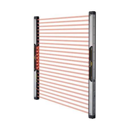
USF4BH36C SF4B-H36C PANASONIC Safety Light Curtain Typ4 (PLe SIL3), Hand Protection, protective height 743,4..
$0.00USD
3688 in stock
Key Specifications
Item:Specifications
PFHD:3.3 × 10⁻⁹(Note) Probability of dangerous failure per hour.
Cable:0.15 mm2(power line: 0.2 mm2) 8-core heat-resistant PVC cable, 5 m16.404 ftlong
MTTFD:100 years or more(Note) Mean time to dangerous failure.
Supplier Information
PANASONIC
Products: 4316
Usually ships within 2-3 business days
Quality Guaranteed
Fast Shipping
Technical Support
Technical Specifications
| Parameter | Value |
|---|---|
| Item | Specifications |
| PFHD | 3.3 × 10⁻⁹(Note) Probability of dangerous failure per hour. |
| Cable | 0.15 mm2(power line: 0.2 mm2) 8-core heat-resistant PVC cable, 5 m16.404 ftlong |
| MTTFD | 100 years or more(Note) Mean time to dangerous failure. |
| Details | Min. sensing object ø25 mm ø0.984 in (20 mm 0.787 in beam pitch) |
| Product | Compact Safety Light Curtain[Type4 PLe SIL3] |
| Material | Enclosure: Polycarbonate |
| Beam pitch | 20 mm0.787 in |
| Accessories | SF4B-TR25 (Test rod): 1 pc. |
| Part Number | SF4B-H36C |
| Product name | Compact Safety Light Curtain[Type4 PLe SIL3] SF4B-C |
| ELCA function | Incorporated (reducing mutual interference automatically) |
| Power voltage | 24 V DC plus or minus 10 % Ripple P-P 10 % or less |
| Response time | OFF response: 14 ms or lessON response: 80 to 90 ms |
| Product Number | SF4B-H36C |
| Cable extension | Extension up to total 50 m164.042 ftis possible for 0.2 mm2or more, cable(Note) When the synchronization+ wire (orange) and synchronization- wire (orange / black) is extended with a cable other than exclusive cable, use a 0.2 mm2or more shielded twisted pair cable. |
| Muting function | - |
| Operating range | 0.3 to 7m0.984 to 22.966 ft(Note) The operating range is the possible setting distance between the emitter and the receiver. |
| Emitting element | Infrared LED (Peak emission wavelength: 850 nm0.033 mil) |
| Pollution degree | 3 |
| Override function | - |
| Protective height | 743.4 mm 29.268 in |
| Interlock function | Incorporated [Manual reset / Auto reset](Note) The manual reset and automatic reset are possible to be switched depending on the wiring status. |
| Operating altitude | 2,000 m6,561.68 ftor less(Note) Do not use or store in an environment pressurized to atmospheric pressure or higher at an altitude of 0 m. |
| Optional functions | Fixed blanking, floating blanking, light emitting amount control, auxiliary output switching, protecting, interlock setting changing, external relay monitor setting changing(Note) In case of using optional function, the handy-controller SFB-HC is required. |
| Ambient illuminance | Incandescent light: 3,500 liter x or less at the light-receiving face |
| Current consumption | Emitter: 75 mA or lessReceiver: 95 mA or less |
| Min. sensing object | ø25 mm ø0.984 in opaque object(Note) In case the blanking function is valid, the operation mode is changed. |
| No. of beam channels | 36 |
| Emission halt function | Incorporated |
| Muting auxiliary output | - |
| Effective aperture angle | plus or minus 2.5℃ or less [for an operating range exceeding 3 m9.843 ft(conforming to IEC 61496-2 / ANSI/UL 61496-2) ] |
| Applicable standards:Japan | JIS B 9704-1 / 2 (Type 4), JIS B 9705-1 (Category 4), JIS C 0508-1 to 3 (SIL3) |
| Applicable standards:Europe | EN 61496-1 (Type 4), EN ISO 13849-1:2015 (Category 4, PLe), EN 61508-1 to 3 (SIL3), EN 55011, EN 50178, EN 61000-6-2(Note) Regarding EU Machinery Directive, a Notified Body, TÜV SÜD, has certified with the type examination certificate. |
| Control outputs (OSSD 1, OSSD 2) | PNP open-collector transistor / NPN open-collector transistor (switching method)• Maximum source current: 200 mA• Applied voltage: Same as supply voltage (between the control output and +V)• Residual voltage: 2.5 V or less (source current 200 mA, when using 20 m65.617 ftlength cable)• Leakage current: 0.1 mA or less (Including power supply OFF condition)• Maximum load capacity: 0.22 micro F (No load to maximum output current)• Load wiring resistance: 3Ωor less• Maximum sink current: 200 mA• Applied voltage: Same as supply voltage (between the control output and 0 V)• Residual voltage: 2.5 V or less (sink current 200 mA, when using 20 m65.617 ftlength cable)• Leakage current: 0.1 mA or less (Including power supply OFF condition)• Maximum load capacity: : 0.22 micro F (No load to maximum output current)• Load wiring resistance: 3Ωor less |
| Applicable standards:North America | ANSI / UL 61496-1 / 2 (Type 4), ANSI / UL 508, CAN / CSA 61496-1 / 2 (Type 4), CAN / CSA C22.2 No.14, OSHA 1910.212, OSHA 1910.217 (C), ANSI B11.1 to B11.19, ANSI / RIA 15.06(Note) With regards to the standards in the US/Canada, a Notified Body, TÜV SÜD, has certified the CTÜVUS mark. |
| External device monitoring function | Incorporated |
| Auxiliary output (Non-safety output) | PNP open-collector transistor / NPN open-collector transistor (switching method)• Maximum source current: 60 mA• Applied voltage: Same as supply voltage (between the auxiliary output and +V)• Residual voltage: 2.5 V or less (source current 60 mA, when using 20 m65.617 ftlength cable)• Maximum sink current: 60 mA• Applied voltage: Same as supply voltage (between the auxiliary output and 0 V)• Residual voltage: 2.5 V or less (sink current 60 mA, when using 20 m65.617 ftlength cable) |
| Large multi-purpose indicator function | - |
| Muting auxiliary output:Operation mode | - |
| Applicable regulations and certifications | CE Marking (Machinery Directive, EMC Directive, RoHS Directive), UKCA Marking [Supply of Machinery (Safety) Regulations, EMC Regulations, RoHS Regulations], TÜV SÜD certification |
| Environmental resistance:Ambient humidity | 30 to 85 % RH, Storage: 30 to 85 % RH |
| Environmental resistance:Shock resistance | 300 m / s2acceleration (30 G approx.) in X, Y and Z directions for three times each |
| Muting auxiliary output:Protection circuit | - |
| Net weight (Total of emitter and receiver) | approx. 1,200 g |
| Applicable standards:International standard | IEC 61496-1 / 2 (Type 4), ISO 13849-1:2015 (Category 4, PLe), IEC 61508-1 to 3 (SIL3) |
| Environmental resistance:Ambient temperature | -10 to +55℃+14 to +131 ℉(No dew condensation or icing allowed), Storage: –25 to +60 ℃–3 to +140 ℉ |
| Environmental resistance:Degree of protection | IP65 (IEC) |
| Environmental resistance:Vibration resistance | 10 to 55 Hz frequency, 0.75 mm0.030 inamplitude in X, Y and Z directions for two hours each |
| Environmental resistance:Insulation resistance | 20 MΩ or more, with 500 V DC megger between all supply terminals connected together and enclosure |
| Control outputs (OSSD 1, OSSD 2):Operation mode | ON when all beam channels are received, OFF when one or more beam channels are interrupted (OFF also in case of any malfunction in the safety light curtain or the synchronization signal)(Note) During muting, control output will not turn off even if the beams are interrupted.(Note) When the blanking function is enabled, the operating mode will change. |
| Control outputs(OSSD1, OSSD2):Protection circuit | Incorporated |
| Environmental resistance:Voltage withstandability | 1,000 V AC for one min. between all supply terminals connected together and enclosure |
| Auxiliary output (Non-safety output):Operation mode | OFF when control outputs are ON, ON when control outputs are OFF (Factory setting, operating mode can be changed using the SFB-HC handy-controller.) |
| Auxiliary output (Non-safety output):Protection circuit | Incorporated |
Product Description
SF4B-C Cat.4 Safety Barrier (PLe SIL3), 20 mm hand-to-beam protection, protected height 743.4 mm, operating range 0.3 to 7m, PNP/NPN, 5m cable, IP65
Key Features
- Industrial grade quality
- RoHS compliant
- CE certified
- 1-year warranty
Product Documents
Datasheet
Technical specifications and performance data
User Manual
Installation and operation guide


