In Stock Hot Product
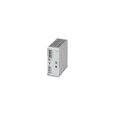
TRIO3-PS/3AC/24DC/20
TRIO3-PS/3AC/24DC/20 1159044 PHOENIX CONTACT Primary switching power supplies, TRIO POWER, Push-in connectio..
$348.17USD
73 in stock
Key Specifications
:2x 400V AC ... 500 V AC ±10%
I/O:asymmetric
Exit:asymmetric 2 kV (Test Severity 3)
Depth:132 mm
Supplier Information
Products: 0
Usually ships within 2-3 business days
Quality Guaranteed
Fast Shipping
Technical Support
Technical Specifications
| Parameter | Value |
|---|---|
| 2x 400V AC ... 500 V AC ±10% | |
| I/O | asymmetric |
| Exit | asymmetric 2 kV (Test Severity 3) |
| Depth | 132 mm |
| Width | 60 mm |
| Yield | Typ. 94.53% (3x 400 V AC) |
| rigid | 0.2 mm² ... 4 mm² |
| Colour | Red, Yellow, Green (Multicolor LED) |
| Height | 135 mm |
| Marked | UL/C-UL Listed UL 61010-1 |
| Signal | asymmetric 1 kV (Test Severity 3) |
| LED off | No supply voltage at Input AC (Off) |
| tension | 10 V (Test Severity 3) |
| Derating | 60 °C ... 70 °C |
| Position | 3.x |
| entrance | asymmetric 2 kV (Test Severity 3) |
| flexible | 0.2 mm² ... 2.5 mm² |
| function | Visual indication of operating status |
| frequency | 50 Hz |
| EN 61010-1 | III (≤ 2000 m) |
| Ascent Time | ≤ 1 sec (UOut= 10% ... 90 %) |
| Criterion A | Normal service behavior within the specified limits. |
| Criterion B | Transient alteration of service behavior, which is corrected by the device itself. |
| Criterion C | Temporary adverse effects on performance that are automatically corrected by the equipment or that can be reset by operating the control elements. |
| Observation | Criterion B |
| Peel Length | 10 mm (rigid/flexible) |
| Rigid (AWG) | 24 ... 12 (Cu) |
| Crest Factor | Typ. 1.51 (3x 400 V AC) |
| Product Type | Power supply |
| Fixing height | ≤ 5000 m (> 2000 m, Derating: 10%/1000 m) |
| Status Status | UOut> 21 V DC & IOutN (Closed Contact) |
| Voltage Error | 70 % |
| EN 61010-2-201 | III (≤ 2000 m) |
| Product Family | TRIO POWER |
| Additional Text | Class 3 |
| Connection type | Push-in connection |
| Frequency Range | 0 kHz ... 2 kHz |
| Residual ripple | Typ. 15 mVPP(with nominal values) |
| Type of signage | LED DC OK - Operating Signal Status (UN= 24 V DC, IOut= IN) |
| Current Capacity | max. 100 mA |
| Number of phases | 3,00 |
| Protection Index | IP20 |
| Rules/Provisions | DIN EN 61558-2-16 |
| Type of mounting | Rail mounting |
| Constant emptying | Yes |
| Dimming deviation | < 1% (static load change 10% ... 90 %) |
| Module Input Fuse | 3.15 A internal (device protection) |
| Network Structure | Star Network (TN, TT, IT (PE)) |
| Number of periods | 25 periods |
| Output Power (PN) | 480 W |
| Switching voltage | MAX 30 V DC (SELV) |
| Current absorption | 3x 0.77 A (3x 400 V AC) |
| Kind of protection | I |
| Protection Circuit | Protection against transients; Varistor |
| Built-in protection | No |
| Degree of pollution | 2 |
| Download contact us | 6 kV (Test Severity 3) |
| Input Voltage Range | 3x 400V AC ... 500 V AC -20% ... +10% |
| Pole Identification | 3.1 (13), 3.2 (14) |
| Crashes (in service) | 18 ms, 30g, for each local address (IEC 60068-2-27) |
| Execution of the cap | Polycarbonate |
| Frequency range (fN) | 50 Hz ... 60 Hz ±10% |
| LED On (Red), ISHORT | UOutOut > 0.9 x IN(on (red), ISHORTS) |
| Test Field Intensity | 10 V/m (Test Severity 3) |
| Interference emission | Interference emission in accordance with EN 61000-6-3 (residential and commercial areas) and EN 61000-6-4 (industrial areas) |
| LED on (green), DC OK | UOut> 21 V DC & IOutN (on (green), DC OK) |
| Low Voltage Directive | Compliance with the Low Voltage Directive 2014/35/EU |
| Position for mounting | Horizontal rail NS 35, EN 60715 |
| Discharge into the air | 8 kV (Test Severity 3) |
| Extra-current shut-off | < 13 A (25 °C) |
| Nominal Output Voltage | 24 V DC |
| Power Factor (cos phi) | 0.93 (3x 480 V AC) |
| Vibration (in service) | 10 Hz ... 50 Hz, amplitude ±0.2 mm (IEC 60068-2-6) |
| Interference resistance | Immunity to interference according to EN 61000-6-1 (domestic use), EN 61000-6-2 (industrial use) |
| Short circuit resistant | Yes |
| Denomination of standard | Safety of power supplies up to 1100 V (isolation distances) |
| Recirculation Resistance | ≤ 35 V DC |
| Standards/Specifications | EN 61000-3-2 |
| Ground Shunt Current (PE) | < 3.5 mA |
| Installation instructions | Alignable: horizontal 0 mm, vertical 30 mm |
| LED On (Red Flashing) OVP | UOUT> OVP (Over voltage protection) (on (flashing red)) |
| Mounting Distance Up/Down | 50 mm / 50 mm |
| Rated Output Current (IN) | 20 A |
| Dynamic Boost (IDyn.Boost) | max. 30 A (5 sec) |
| MTBF (IEC 61709, SN 29500) | > 1100000 h (25 °C) |
| Output Power (PDyn. Boost) | max. 720 W (5 sec) |
| LED On (Yellow), IOut > 90% | UOut> 21 V DC & IOut> 0.9 x IN(on (yellow), IOut> 90%) |
| Nominal Input Voltage Range | 3x 400V AC ... 500 V AC |
| Radiated spurious emissions | EN 55016 |
| Supply Voltage Voltage Type | AC |
| Parallel connection possible | Yes, to increase power and redundancy with diode |
| Right/Left Mounting Distance | 0 mm / 0 mm |
| Typical Country Grid Voltage | 3x 400V AC |
| Ambient Temperature (Service) | -25 °C ... 70 °C (> 60 °C Derating: 2.5%/K) |
| Electromagnetic compatibility | Compliance with EMC Directive 2014/30/EU |
| Inrush current integral (I2t) | < 0.33 A2s |
| Network Failure Bridging Time | Typ. 28 ms (3x 400 V AC) |
| Output Surge Protection (OVP) | ≤ 35 V DC |
| Execution of the side elements | aluminium |
| Maximum Rated Load Dissipation | < 27.35 W (3x 480 V AC) |
| Input/Output Insulation Voltage | 4 kV AC (type test) |
| Maximum Open Circuit Dissipation | < 3.1 W (3x 480 V AC) |
| Possibility of series connection | yes, to increase the tension (observe the SELV limit) |
| Emission of Conducted Interference | EN 55016 |
| Environmental Protection Directive | RoHS Directive 2011/65/EU |
| Flexible toe cap with plastic cuff | 0.25 mm² ... 1.5 mm² |
| Flammability class according to UL 94 | V0 (Housing, terminals) |
| Switching contact (without potential) | OptoMOS |
| Output Voltage Adjustment Range (Uset) | 24 V DC ... 28 V DC (> 24 V DC, limited by power constant) |
| Power Dissipated at Minimum Rated Load | < 26.08 W (3x 400 V AC) |
| Ambient Temperature (Storage/Transport) | -40 °C ... 85 °C |
| Flexible toe cap without plastic sleeve | 0.25 mm² ... 2.5 mm² |
| Max. permissible air humidity (service) | ≤ 95% (at 25°C, non-condensing) |
| Minimum power dissipated in vacuum mode | < 3 W (3x 400 V AC) |
| Ambient temperature (Start-Up tested model) | -40 °C |
| Selecting the Right Fuse for Ingress Protection | 3x 6 A ... 16 A (Characteristic B, C, D, K or comparable) |
Product Description
Primary Switching Power Supplies, TRIO POWER, Push-in Connection, Rail Mount, Input: 3-Phase, Output: 24 VDC / 20 A
Key Features
- Industrial grade quality
- RoHS compliant
- CE certified
- 1-year warranty
Product Documents
Datasheet
Technical specifications and performance data
User Manual
Installation and operation guide


