In Stock Hot Product
ST-OV3-24DC/400AC/3
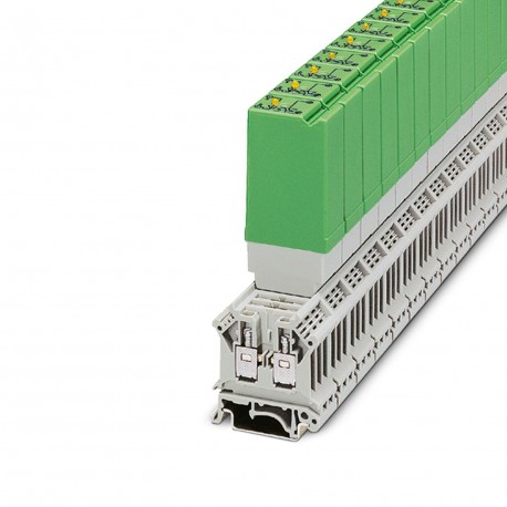
ST-OV3- 24DC/400AC/3 2905417 PHOENIX CONTACT Solid-state relays
$0.00USD
4641 in stock
Key Specifications
:RC element; RC element
Color:green (RAL 6021)
Depth:112 mm
Width:20.8 mm
Supplier Information
Products: 0
Usually ships within 2-3 business days
Quality Guaranteed
Fast Shipping
Technical Support
Technical Specifications
| Parameter | Value |
|---|---|
| RC element; RC element | |
| Color | green (RAL 6021) |
| Depth | 112 mm |
| Width | 20.8 mm |
| Height | 42.5 mm |
| Insulation | Basic insulation |
| Product type | Single solid-state relay |
| Surge current | 125 A (t = 10 ms) |
| Leakage current | approx. 12 mA |
| Article revision | 07 |
| Pollution degree | 2 |
| Min. load current | 50 mA |
| Mounting position | Horizontal DIN rail |
| Protective circuit | Reverse polarity protection |
| Input voltage range | 21.6 V DC ... 26.4 V DC |
| Output voltage range | 24 V AC ... 420 V AC |
| Overvoltage category | III |
| Peak offstate voltage | 800 V (Periodic peak reverse voltage) |
| Standards/regulations | IEC 60664 |
| Maximum inrush current | 125 A (t = 10 ms) |
| Output nominal voltage | 400 V AC |
| Transmission frequency | 10 Hz |
| Design of digital output | electronic |
| Nominal input voltage UN | 24 V DC |
| Operating voltage display | Yellow LED |
| Limiting continuous current | 3 A (see derating curve) |
| Test voltage (Input/output) | 2.5 kV AC (Input/output) |
| Typical input current at UN | 7 mA |
| Date of last data management | 22.05.2024 |
| Ambient temperature (operation) | 0 °C ... 60 °C |
| Input voltage range in reference to UN | 0.9 ... 1.1 |
| Ambient temperature (storage/transport) | 0 °C ... 70 °C |
| Maximum power dissipation for nominal condition | 0.17 W |
| Voltage drop at max. limiting continuous current | ≤ 1.2 V |
| Switching threshold "0" signal in reference to UN | ≤ 0.4 |
| Switching threshold "1" signal in reference to UN | ≥ 0.8 |
Product Description
Power solid-state plug-in relay, input: 24 V DC, output: 24-420 V AC/max. 3 A
Key Features
- Industrial grade quality
- RoHS compliant
- CE certified
- 1-year warranty
Product Documents
Datasheet
Technical specifications and performance data
User Manual
Installation and operation guide


