In Stock Hot Product
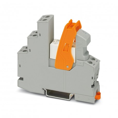
RIF-1-RSC-LDP-24DC/1IC
RIF-1-RSC-LDP-24DC/1IC 2909885 PHOENIX CONTACT Relay Module
$0.00USD
4372 in stock
Key Specifications
:10 A (Value is permissible if connections 11 and 21, as well as connections 14 and 24 are bridged.)
Color:gray (RAL 7042)
Depth:75 mm
Width:16 mm
Supplier Information
Products: 0
Usually ships within 2-3 business days
Quality Guaranteed
Fast Shipping
Technical Support
Technical Specifications
| Parameter | Value |
|---|---|
| 10 A (Value is permissible if connections 11 and 21, as well as connections 14 and 24 are bridged.) | |
| Color | gray (RAL 7042) |
| Depth | 75 mm |
| Width | 16 mm |
| Height | 90 mm |
| Altitude | ≤ 2000 m |
| Insulation | Safe isolation, reinforced insulation |
| Application | high inrush currents |
| Coil voltage | 24 V DC |
| Product type | Relay Module |
| Assembly note | in rows with zero spacing |
| Mounting type | DIN rail mounting |
| Identification | ISA-S71.04. G3 Harsh Group |
| Operating mode | 100% operating factor |
| Product family | RIFLINE complete |
| Article revision | 05 |
| Contact material | AgSnO |
| Drive (polarity) | polarized |
| Pollution degree | 2 |
| Stripping length | 8 mm |
| Connection method | Screw connection |
| Mounting position | any |
| Tightening torque | 0.5 Nm ... 0.6 Nm |
| Drive and function | monostable |
| Notes on operation | FBS 2-6... plug-in bridge for the input side (A2) and FBS-2-8... plug-in bridge for the output side (11/21) |
| Protective circuit | Freewheeling diode; Freewheeling diode |
| Input voltage range | 19.2 V DC ... 33.6 V DC (20 °C) |
| Rated surge voltage | 6 kV |
| Overvoltage category | III |
| Typical release time | 10 ms |
| Standards/regulations | IEC 60947-5-1 |
| Typical response time | 8 ms |
| Contact switching type | 1 N/O contact |
| Maximum inrush current | 80 A (20 ms) |
| Min. switching current | 100 mA (12 V DC) |
| Type of switch contact | Single contact |
| Mechanical service life | 3x 10⁷cycles |
| Switching capacity min. | 1200 mW |
| Nominal input voltage UN | 24 V DC |
| Rated insulation voltage | 250 V AC |
| Maximum switching voltage | 250 V AC/DC (The separating plate PLC-ATP should be installed for voltages larger than 250 V (L1, L2, L3) between identical terminal blocks in adjacent modules. Potential bridging is then carried out with FBST 8-PLC... or ...FBST 500...) |
| Minimum switching voltage | 12 V (100 mA) |
| Operating voltage display | Yellow LED |
| Conductor cross section AWG | 20 ... 10 (solid) |
| Limiting continuous current | 6 A |
| Typical input current at UN | 18 mA |
| Date of last data management | 21.08.2024 |
| Degree of protection (Relay) | RT II (Relay) |
| Conductor cross section rigid | 0.5 mm² ... 4 mm² |
| Test voltage (Winding/contact) | 4 kV AC (50 Hz, 1 min., winding/contact) |
| Ambient temperature (operation) | -40 °C ... 70 °C |
| Conductor cross section flexible | 0.5 mm² ... 4 mm² |
| Degree of protection (Relay base) | IP20 (Relay base) |
| Interrupting rating (ohmic load) max. | 264 W (at 24 V DC, observe contact derating) |
| Input voltage range in reference to UN | see diagram |
| Ambient temperature (storage/transport) | -40 °C ... 85 °C |
| Degree of protection (Installation location) | ≥ IP54 (Installation location) |
| Maximum power dissipation for nominal condition | 0.43 W |
| Utilization category CB Scheme (IEC 60947-5-1) | AC15, 6 A/250 V (N/O contact) |
| Conductor cross-section rigid (2 conductors with same cross section) | 0.5 mm² ... 2.5 mm² |
| Conductor cross section flexible (2 conductors with same cross section) | 0.5 mm² ... 2.5 mm² |
Product Description
Pre-assembled relay module with screw connection, consisting of: relay socket, relay with power contact, plug-in indication/antiparasitic module and clamping flange. Contact version: 1 normally open c
Key Features
- Industrial grade quality
- RoHS compliant
- CE certified
- 1-year warranty
Product Documents
Datasheet
Technical specifications and performance data
User Manual
Installation and operation guide


