In Stock Hot Product
PTFIX 12X2,5-NS35A BN
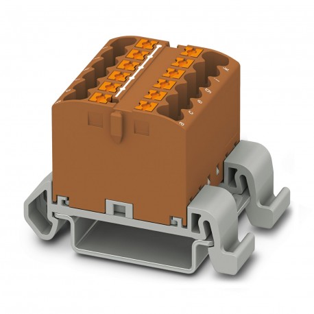
PTFIX 12X2,5-NS35A BN 3273164 PHOENIX CONTACT Distribution block
$0.00USD
3718 in stock
Key Specifications
:For versions with 6 or 7 connections, it is enough to place one DIN rail adapter centrally per block and place flange elements after every other block.
Note:The maximum load current of a single clamping unit must not be exceeded.
Color:brown (RAL 8028)
Width:31.5 mm
Supplier Information
Products: 0
Usually ships within 2-3 business days
Quality Guaranteed
Fast Shipping
Technical Support
Technical Specifications
| Parameter | Value |
|---|---|
| For versions with 6 or 7 connections, it is enough to place one DIN rail adapter centrally per block and place flange elements after every other block. | |
| Note | The maximum load current of a single clamping unit must not be exceeded. |
| Color | brown (RAL 8028) |
| Width | 31.5 mm |
| Height | 45.7 mm |
| Result | Test passed |
| Spectrum | Service life test category 2, bogie-mounted |
| ASD level | 6.12 (m/s²)²/Hz |
| Frequency | f1= 5 Hz to f2= 250 Hz |
| Potentials | 1 |
| Pulse shape | Half-sine |
| Revolutions | 135 |
| Acceleration | 3.12g |
| Product type | Distributor terminal block |
| Mounting type | NS 35/7,5 |
| Specification | DIN EN 50155 (VDE 0115-200):2008-03 |
| Number of rows | 1 |
| Rotation speed | 10 rpm |
| Shock duration | 18 ms |
| Nominal current | 24 A |
| Nominal voltage | 690 V |
| Open side panel | No |
| Test directions | X-, Y- and Z-axis |
| Article revision | 05 |
| Stripping length | 8 mm ... 10 mm |
| Time of exposure | 30 s |
| Cross section AWG | 26 ... 12 (converted acc. to IEC) |
| Notes on operation | the blocks can be bridged with one another via the conductor shaft, for corresponding plug-in bridges, see accessories |
| Temperature cycles | 192 |
| Degree of pollution | 3 |
| Depth on NS 35/7,5 | 30.9 mm |
| Insulating material | PA |
| Rated surge voltage | 8 kV |
| Test force setpoint | 1 N |
| Maximum load current | 32 A |
| Overvoltage category | III |
| Maximum total current | 48 A |
| Nominal cross section | 2.5 mm² |
| Number of connections | 12 |
| Test voltage setpoint | 9.8 kV |
| Test duration per axis | 5 h |
| DIN rail/fixing support | NS 35 |
| Rated cross section AWG | 14 |
| Insulating material group | I |
| Internal cylindrical gage | A3 |
| Conductor cross section rigid | 0.14 mm² ... 4 mm² |
| Ambient temperature (assembly) | -5 °C ... 70 °C |
| Conductor cross section/weight | 0.14 mm² / 0.2 kg |
| Number of shocks per direction | 3 |
| Ambient temperature (actuation) | -5 °C ... 70 °C |
| Ambient temperature (operation) | -60 °C ... 110 °C (Operating temperature range incl. self-heating; for max. short-term operating temperature, see RTI Elec.) |
| Number of connections per level | 12 |
| Conductor cross section flexible | 0.14 mm² ... 2.5 mm² |
| Connection in acc. with standard | IEC 60947-7-1 |
| Permissible humidity (operation) | 20 % ... 90 % |
| Requirement temperature-rise test | Increase in temperature ≤ 45 K |
| Short-time withstand current 4 mm² | 0.48 kA |
| Conductor cross section, rigid [AWG] | 24 ... 12 (converted acc. to IEC) |
| Short-time withstand current 2.5 mm² | 0.3 kA |
| Flammability rating according to UL 94 | V0 |
| Smoke gas toxicity NFPA 130 (SMP 800C) | passed |
| Ambient temperature (storage/transport) | -25 °C ... 60 °C (for a short time, no longer than 24 h, -60°C to +70°C) |
| Conductor cross section, flexible [AWG] | 26 ... 14 (converted acc. to IEC) |
| Permissible humidity (storage/transport) | 30 % ... 70 % |
| Surface flammability NFPA 130 (ASTM E 162) | passed |
| Static insulating material application in cold | -60 °C |
| Maximum power dissipation for nominal condition | 0.77 W |
| Calorimetric heat release NFPA 130 (ASTM E 1354) | 28 MJ/kg |
| Fire protection for rail vehicles (DIN EN 45545-2) R22 | HL 1 - HL 3 |
| Fire protection for rail vehicles (DIN EN 45545-2) R23 | HL 1 - HL 3 |
| Fire protection for rail vehicles (DIN EN 45545-2) R24 | HL 1 - HL 3 |
| Fire protection for rail vehicles (DIN EN 45545-2) R26 | HL 1 - HL 3 |
| Specific optical density of smoke NFPA 130 (ASTM E 662) | passed |
| Flexible conductor cross section (ferrule with plastic sleeve) | 0.14 mm² ... 2.5 mm² |
| Relative insulation material temperature index (Elec., UL 746 B) | 130 °C |
| Conductor cross-section flexible (ferrule without plastic sleeve) | 0.14 mm² ... 2.5 mm² |
| Temperature index of insulation material (DIN EN 60216-1 (VDE 0304-21)) | 130 °C |
Product Description
Distribution block, Block with horizontal alignment, nominal voltage: 690 V, nominal current: 24 A, number of connections: 12, connection type: Push-in connection, section: 0.14 mm² - 4 mm², mounting
Key Features
- Industrial grade quality
- RoHS compliant
- CE certified
- 1-year warranty
Product Documents
Datasheet
Technical specifications and performance data
User Manual
Installation and operation guide


