In Stock Hot Product
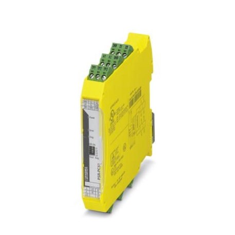
PSR-PC51-1NO-1NC-24DC-SC
PSR-PC51-1NO-1NC-24DC-SC 2702522 PHOENIX CONTACT Coupling relay
$0.00USD
3690 in stock
Key Specifications
GTIN:4055626283388
Orderkey:2702522
Depth (Note):114.5 mm
Packing unit:1 pc
Supplier Information
Products: 0
Usually ships within 2-3 business days
Quality Guaranteed
Fast Shipping
Technical Support
Technical Specifications
| Parameter | Value |
|---|---|
| GTIN | 4055626283388 |
| Orderkey | 2702522 |
| Depth (Note) | 114.5 mm |
| Packing unit | 1 pc |
| Width (Note) | 17.5 mm |
| Height (Note) | 112.2 mm |
| (Power supply) | typ. 30 mA (Input TP3) |
| (Digital inputs) | max. 5 A (Δt 1 s) |
| Country of origin | DE (Germany) |
| Net weight (Times) | 147.48 g |
| Relay type (Times) | Electromechanical relay |
| pluggable (General) | Yes |
| Custom tariff number | 85364190 |
| (Ambient conditions) | Polarity reversal protection for rated control circuit supply voltage and diagnostic supply voltage |
| Housing color (Times) | yellow |
| Mounting type (Times) | DIN rail mounting |
| Screw thread (General) | M3 |
| Status display (Times) | 1 x yellow LED, 1 x green LED, 1 x red LED |
| Housing material (Times) | Frianyl A 63 R V0 |
| Mounting position (Times) | vertical or horizontal |
| Stripping length (General) | 7 mm |
| Connection method (General) | Screw connection |
| Degree of protection (Times) | IP20 |
| Output name (Digital inputs) | Enabling current path |
| Assembly instructions (Times) | See derating curve |
| Contact type (Digital inputs) | 1 enabling current path |
| Designation (Connection data) | EN 50156-2 |
| Inrush current (Power supply) | typ. 200 mA |
| Maximum altitude (Dimensions) | ≤ 2000 m (Above sea level) |
| Nominal operating mode (Times) | 100% operating factor |
| Inrush current (Digital inputs) | min. 50 mA |
| Number of inputs (Power supply) | 3 |
| Filter time (Ambient conditions) | 2 ms (at A1-A2 in the event of voltage dips at Us) |
| Contact material (Digital inputs) | AgNi, gold-flashed, Ag alloy |
| Type of protection (Power supply) | Surge protection |
| Current consumption (Power supply) | typ. 20 mA (Input TP1) |
| Number of outputs (Digital inputs) | 1 (undelayed) |
| Sq. Total current (Digital inputs) | 9 A2(observe derating) |
| Switching voltage (Digital inputs) | min. 16 V AC/DC |
| Inrush current (Ambient conditions) | max. 100 mA |
| Output description (Digital inputs) | safety-related N/O contacts |
| Switching capacity (Digital inputs) | min. 1 W |
| Switching frequency (Digital inputs) | max. 0.5 Hz |
| Weight per Piece (excluding packing) | 147.480 g |
| (Safety-related characteristic data) | Safe isolation, 6 kV reinforced insulation from (A1/A2, 24V/0V, 21/22, and TP1/TP2/TP3) to the enabling current path (L, L', LO, LO', NI, NI', N,N') |
| Air pressure (operation) (Dimensions) | 79 kPa ... 106 kPa |
| Diagnostic threshold (Digital inputs) | 7 Ω ... 20 kΩ (configurable) |
| REACh SVHC (Standards and Regulations) | Lead 7439-92-1 |
| Description of the input (Power supply) | Test point for proof test |
| Protective circuit (Ambient conditions) | Surge protection 36 V suppressor diode (A1-A2)33 V suppressor diode (24V-GND) |
| Input current at UD (Ambient conditions) | 35 mA (at UD= 24 V) |
| Mechanical service life (Digital inputs) | approx. 5x 10⁷cycles |
| Inrush current at UD (Ambient conditions) | 1.5 A (Δt |
| Conductor cross section AWG max. (General) | 12 |
| Conductor cross section AWG min. (General) | 24 |
| Shock (Safety-related characteristic data) | 15g, 11 ms |
| Protective circuit/component (Power supply) | 36 V suppressor diode |
| Ambient temperature (operation) (Dimensions) | -25 °C ... 60 °C (observe derating) |
| Conductor cross section solid max. (General) | 2.5 mm² |
| Conductor cross section solid min. (General) | 0.2 mm² |
| Limiting continuous current (Digital inputs) | 3 A (Observe derating, load type, and on-load voltage) |
| Power consumption at UD (Ambient conditions) | typ. 0.9 W (at UD; Off state) |
| Power consumption at US (Ambient conditions) | typ. 2 W (at US/UD; On state) |
| Air pressure (storage/transport) (Dimensions) | 79 kPa ... 106 kPa |
| Utilization restriction (Key Commercial Data) | EMC: class A product, see manufacturer's declaration in the download area |
| Safety Integrity Level (SIL) (Connection data) | 3 (Reference IEC 61508) |
| Conductor cross section flexible max. (General) | 2.5 mm² |
| Conductor cross section flexible min. (General) | 0.2 mm² |
| Conformance (Safety-related characteristic data) | CE-compliant |
| Designation (Safety-related characteristic data) | Air clearances and creepage distances between the power circuits |
| Diagnostic supply voltage UD (Ambient conditions) | 24 V DC -20 % / +25 % |
| Output name (Relay outputs: enabling current path) | Signaling current path |
| Contact type (Relay outputs: enabling current path) | 1 signaling current path |
| Min. degree of protection of inst. location (Times) | IP54 |
| Ambient temperature (storage/transport) (Dimensions) | -40 °C ... 65 °C |
| Rated control supply current IS (Ambient conditions) | typ. 75 mA |
| Inrush current (Relay outputs: enabling current path) | max. 800 mA (Δt 100 ms) |
| Degree of pollution (Safety-related characteristic data) | 2 |
| Number of outputs (Relay outputs: enabling current path) | 1 (without delay, floating) |
| Output description (Relay outputs: enabling current path) | non-safety-related N/C contact |
| Overvoltage category (Safety-related characteristic data) | III |
| Max. permissible humidity (storage/transport) (Dimensions) | 75 % (on average, 85% infrequently, non-condensing) |
| Standards/regulations (Safety-related characteristic data) | DIN EN 50178 |
| Vibration (operation) (Safety-related characteristic data) | 10 Hz ...150 Hz, 2g |
| Max. permissible relative humidity (operation) (Dimensions) | 75 % (on average, 85% infrequently, non-condensing) |
| Rated control circuit supply voltage US (Ambient conditions) | 24 V DC -15 % / +10 % |
| Rated insulation voltage (Safety-related characteristic data) | 250 V AC |
| Short-circuit protection (Relay outputs: enabling current path) | no |
| Environmental simulation test (Safety-related characteristic data) | ISA-S71.04 (G3) |
| Rated surge voltage/insulation (Safety-related characteristic data) | Basic insulation 4 kV between all current paths and housing |
| Recovery time (Relay outputs: return current/signaling current path) | 1 s (when controlled via A1-A2) |
| Typical pickup time at US (Relay outputs: return current/signaling current path) | typ. 100 ms (when controlled via A1-A2) |
| Typical release time at US (Relay outputs: return current/signaling current path) | typ. 30 ms (when controlled via A1-A2) |
Product Description
Coupling relay for galvanic separation and power matching for SIL 3 F&G applications, low demand, load diagnostics in the Off and On state on cable break and short circuit, 1 trip circuit, test pulse
Key Features
- Industrial grade quality
- RoHS compliant
- CE certified
- 1-year warranty
Product Documents
Datasheet
Technical specifications and performance data
User Manual
Installation and operation guide


