In Stock Hot Product
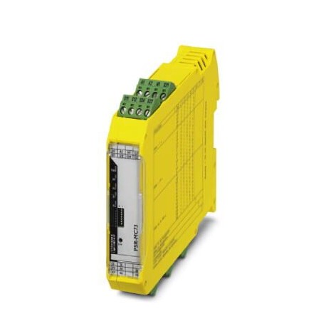
PSR-MC73-5NO-1DO-24DC-SC
PSR-MC73-5NO-1DO-24DC-SC 1015533 PHOENIX CONTACT Safety relay for emergency stop, safety doors, photoelectri..
$0.00USD
3504 in stock
Key Specifications
GTIN:4055626496740
Orderkey:1015533
(Drawings):
Catalog page:Page 227 (C-6-2019)
Supplier Information
Products: 0
Usually ships within 2-3 business days
Quality Guaranteed
Fast Shipping
Technical Support
Technical Specifications
| Parameter | Value |
|---|---|
| GTIN | 4055626496740 |
| Orderkey | 1015533 |
| (Drawings) | |
| Catalog page | Page 227 (C-6-2019) |
| Depth (Note) | 114.5 mm |
| Packing unit | 1 pc |
| Width (Note) | 22.5 mm |
| Height (Note) | 112.2 mm |
| (Power supply) | max. 1 Hz |
| (Alarm outputs) | non-safety-related |
| (Clock outputs) | < 5 ms (when controlled via A1; applicative deactivation via A1/A2 is not permitted) |
| Torque (General) | 0.5 Nm ... 0.6 Nm |
| (Digital inputs) | 4 A gL/gG (for low-demand applications) |
| Country of origin | DE (Germany) |
| ETIM 5.0 (eCl@ss) | EC001449 |
| ETIM 6.0 (eCl@ss) | EC001449 |
| ETIM 7.0 (eCl@ss) | EC001449 |
| (Connection data) | 1 |
| Net weight (Times) | 155.43 g |
| Relay type (Times) | Electromechanical relay with forcibly guided contacts in accordance with IEC/EN 61810-3 (EN 50205) |
| pluggable (General) | Yes |
| Custom tariff number | 85371098 |
| Housing color (Times) | yellow |
| Mounting type (Times) | DIN rail mounting |
| Screw thread (General) | M3 |
| Status display (Times) | 5 x bi-color LED |
| Current (Alarm outputs) | max. 100 mA |
| Voltage (Alarm outputs) | corresponds to US |
| Block diagram (Drawings) | |
| Housing material (Times) | PBT |
| Input name (Power supply) | Start circuit |
| Mounting position (Times) | vertical or horizontal |
| Category (Connection data) | 4 |
| Filter time (Power supply) | max. 3 ms (Test pulse width of low test pulses) |
| Stripping length (General) | 7 mm |
| Connection method (General) | Screw connection |
| Designation (Alarm outputs) | S11, S21 |
| (Standards and Regulations) | For details about hazardous substances go to tab “Downloads”, Category “Manufacturer's declaration” |
| Cable length (Alarm outputs) | max. 150 m |
| Degree of protection (Times) | IP20 |
| Output fuse (Digital inputs) | 6 A gL/gG |
| Output name (Digital inputs) | Enabling current paths |
| Restart time (Clock outputs) | < 1 s (Boot time) |
| eCl@ss 8.0 (Classifications) | 27371819 |
| eCl@ss 9.0 (Classifications) | 27371819 |
| Assembly instructions (Times) | See derating curve |
| Contact type (Digital inputs) | 5 enabling current paths |
| Designation (Connection data) | EN 62061 |
| Inrush current (Power supply) | < 8.6 mA (typically with US) |
| Maximum altitude (Dimensions) | ≤ 2000 m (Above sea level) |
| Recovery time (Clock outputs) | 500 ms (following demand of the safety function) |
| Limit frequency (Power supply) | min. 0 Hz |
| Nominal operating mode (Times) | 100% operating factor |
| Inrush current (Digital inputs) | min. 3 mA |
| Number of inputs (Power supply) | 1 |
| Stop category (Connection data) | 0 |
| Delay time range (Clock outputs) | 0.2 s ... 300 s ±5 % (can be set for 47/48/58) |
| Designation (Ambient conditions) | A1/A2 |
| Filter time (Ambient conditions) | 10 ms (For the logic. At A1 in the event of voltage dips at Us) |
| Contact material (Digital inputs) | AgSnO2 |
| Number of outputs (Alarm outputs) | 2 |
| Current consumption (Power supply) | < 3.2 mA (typically with US) |
| Number of outputs (Digital inputs) | 3 (undelayed: 13/14, 23/24/34) |
| Output description (Alarm outputs) | PNP |
| Sq. Total current (Digital inputs) | 108 A2(observe derating) |
| Switching voltage (Digital inputs) | min. 12 V AC/DC |
| Utilization restriction (Drawings) | EMC: class A product, see manufacturer's declaration in the download area |
| Inrush current (Ambient conditions) | typ. 28 A (Δt = 30 µs at Us) |
| Output description (Digital inputs) | 2 N/O contacts each in series, safety-related, floating |
| Switching capacity (Digital inputs) | min. 60 mW |
| Concurrence input 1/2 (Power supply) | ∞ |
| Switching frequency (Digital inputs) | 0.5 Hz (depending on the set delay time) |
| Weight per Piece (excluding packing) | 240.000 g |
| (Safety-related characteristic data) | Safe isolation, reinforced insulation 6 kV between (A1, A2, S11, S12, S21, S22, S34, M1) and enabling current path (13/14) and enabling current path (23/24/34) and enabling current path (47/48/58) |
| China RoHS (Standards and Regulations) | Environmentally Friendly Use Period = 50 |
| Maximum inrush current (Alarm outputs) | 500 mA (Δt = 10 ms at Us) |
| REACh SVHC (Standards and Regulations) | Lead 7439-92-1 |
| (Relay outputs: enabling current path) | non-safety-related |
| Description of the input (Power supply) | non-safety-related |
| Protective circuit (Ambient conditions) | Serial protection against polarity reversal Suppressor diode |
| Mechanical service life (Digital inputs) | 10x 106cycles |
| Performance level (PL) (Connection data) | e (4 A DC13; 5 A AC15; 8760 switching cycles/year) |
| Short-circuit protection (Alarm outputs) | Yes |
| Typical pickup time at US (Clock outputs) | 500 ms (with Uswhen controlled via A1) |
| Conductor cross section AWG max. (General) | 12 |
| Conductor cross section AWG min. (General) | 24 |
| Shock (Safety-related characteristic data) | 10g (operation), 15g (transport) |
| Typical release time at US (Clock outputs) | < 25 ms (when controlled via S12 and S22 (only for undelayed contacts)) |
| Protective circuit/component (Power supply) | Varistor |
| Typical response time at US (Clock outputs) | < 40 ms (automatic start) |
| Ambient temperature (operation) (Dimensions) | -35 °C ... 60 °C (observe derating) |
| Conductor cross section solid max. (General) | 2.5 mm² |
| Conductor cross section solid min. (General) | 0.2 mm² |
| Limiting continuous current (Digital inputs) | 6 A |
| Power consumption at US (Ambient conditions) | typ. 1.92 W |
| Protective circuit/component (Alarm outputs) | Suppressor diode |
| Input current range "0" signal (Power supply) | 0 mA ... 2 mA |
| Input voltage range "0" signal (Power supply) | 0 V DC ... 5 V DC |
| Input voltage range "1" signal (Power supply) | 11 V DC ... 30 V DC |
| Current (Relay outputs: enabling current path) | max. 100 mA |
| Safety Integrity Level (SIL) (Connection data) | 3 |
| Voltage (Relay outputs: enabling current path) | approx. 23 V DC (US- 1 V) |
| Conductor cross section flexible max. (General) | 2.5 mm² |
| Conductor cross section flexible min. (General) | 0.2 mm² |
| Conformance (Safety-related characteristic data) | CE-compliant |
| Designation (Safety-related characteristic data) | Air clearances and creepage distances between the power circuits |
| Designation (Relay outputs: enabling current path) | M1 |
| Min. degree of protection of inst. location (Times) | IP54 |
| Ambient temperature (storage/transport) (Dimensions) | -40 °C ... 85 °C |
| Rated control supply current IS (Ambient conditions) | typ. 80 mA |
| Degree of pollution (Safety-related characteristic data) | 2 |
| Number of outputs (Relay outputs: enabling current path) | 1 |
| Output description (Relay outputs: enabling current path) | PNP |
| Overvoltage category (Safety-related characteristic data) | III |
| Max. permissible humidity (storage/transport) (Dimensions) | 75 % (on average, 85% infrequently, non-condensing) |
| Standards/regulations (Safety-related characteristic data) | DIN EN 50178 |
| Vibration (operation) (Safety-related characteristic data) | 10 Hz ... 150 Hz, 2g |
| Max. permissible relative humidity (operation) (Dimensions) | 75 % (on average, 85% infrequently, non-condensing) |
| Max. permissible overall conductor resistance (Power supply) | 150 Ω |
| Rated control circuit supply voltage US (Ambient conditions) | 24 V DC -20 % / +25 % |
| Maximum inrush current (Relay outputs: enabling current path) | 500 mA (Δt = 10 ms at Us) |
| Rated insulation voltage (Safety-related characteristic data) | 250 V AC |
| Safety Integrity Level Claim Limit (SIL CL) (Connection data) | 3 |
| Switching capacity according to IEC 60947-5-1 (Digital inputs) | 4 A (24 V (DC13)) |
| Short-circuit protection (Relay outputs: enabling current path) | Yes |
| Protective circuit/component (Relay outputs: enabling current path) | Suppressor diode |
| Rated surge voltage/insulation (Safety-related characteristic data) | Basic insulation 4 kV between all current paths and housing |
Product Description
Safety relay for emergency stop, safety doors, light curtains up to SIL 3, category 4, PL e, 1 or 2 channel operation, transverse short circuit detection, reactivatable, return/excitation delay from 0
Key Features
- Industrial grade quality
- RoHS compliant
- CE certified
- 1-year warranty
Technical Details
Block diagram
Product Documents
Datasheet
Technical specifications and performance data
User Manual
Installation and operation guide


