In Stock Hot Product
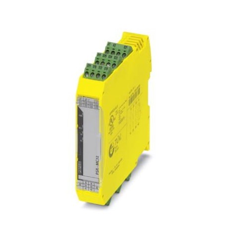
PSR-MC32-3NO-1NC-24-230UC-SP
PSR-MC32-3NO-1NC-24-230UC-SP 2700525 PHOENIX CONTACT Safety relays
$0.00USD
4353 in stock
Key Specifications
GTIN:4046356912709
Orderkey:2700525
Catalog page:Page 253 (C-6-2017)
Depth (Note):114.5 mm
Supplier Information
Products: 0
Usually ships within 2-3 business days
Quality Guaranteed
Fast Shipping
Technical Support
Technical Specifications
| Parameter | Value |
|---|---|
| GTIN | 4046356912709 |
| Orderkey | 2700525 |
| Catalog page | Page 253 (C-6-2017) |
| Depth (Note) | 114.5 mm |
| Packing unit | 1 pc |
| Width (Note) | 22.5 mm |
| Height (Note) | 117.4 mm |
| (Power supply) | Test pulse rate = 5 x Test pulse width |
| (Digital inputs) | 4 A gL/gG (for low-demand applications) |
| Country of origin | DE (Germany) |
| Net weight (Times) | 235.4 g |
| Relay type (Times) | Electromechanical relay with forcibly guided contacts in accordance with EN 50205 |
| pluggable (General) | Yes |
| Custom tariff number | 85371098 |
| (Ambient conditions) | 2.9 W (with AC) |
| Housing color (Times) | yellow |
| Mounting type (Times) | DIN rail mounting |
| Status display (Times) | 3 x green LED |
| Housing material (Times) | PBT |
| Mounting position (Times) | vertical or horizontal |
| Category (Connection data) | 4 (5 A DC13; 5 A AC15; 8760 switching cycles/year) |
| Filter time (Power supply) | max. 1.5 ms (to S10-S12; test pulse width; at 24 V DC) |
| Stripping length (General) | 8 mm |
| Connection method (General) | Spring-cage connection |
| (Standards and Regulations) | No hazardous substances above threshold values |
| Degree of protection (Times) | IP20 |
| Output fuse (Digital inputs) | 6 A gL/gG |
| Output name (Digital inputs) | Enabling current path |
| Assembly instructions (Times) | See derating curve |
| Contact type (Digital inputs) | 3 enabling current paths |
| Designation (Connection data) | EN ISO 13849 |
| Inrush current (Power supply) | < 5 mA (with Us/Ixat S10/S12/S13) |
| Maximum altitude (Dimensions) | ≤ 2000 m (Above sea level) |
| Nominal operating mode (Times) | 100% operating factor |
| Inrush current (Digital inputs) | min. 10 mA |
| Stop category (Connection data) | 0 |
| Filter time (Ambient conditions) | 2 ms (at A1 in the event of voltage dips at Us) |
| Contact material (Digital inputs) | AgSnO2 |
| Operating voltage display (Times) | 1 x green LED |
| Type of protection (Power supply) | Inputs: protection against polarity reversal, surge protection |
| Current consumption (Power supply) | < 5 mA (at Us/Ixto S10/S12/S13/S34/S35) |
| Number of outputs (Digital inputs) | 3 (undelayed) |
| Sq. Total current (Digital inputs) | 72 A2(observe derating) |
| Switching voltage (Digital inputs) | min. 5 V AC/DC |
| Apparent power (Ambient conditions) | typ. 5 VA (at US) |
| Inrush current (Ambient conditions) | < 80 A (Δt = 50 µs at Us) |
| Output description (Digital inputs) | safety-related N/O contacts |
| Switching capacity (Digital inputs) | min. 50 mW |
| Concurrence input 1/2 (Power supply) | ∞ |
| Switching frequency (Digital inputs) | max. 1 Hz |
| Weight per Piece (excluding packing) | 235.400 g |
| (Safety-related characteristic data) | Safe isolation, reinforced insulation 6 kV between all other circuits |
| China RoHS (Standards and Regulations) | Environmentally friendly use period: unlimited = EFUP-e |
| REACh SVHC (Standards and Regulations) | Lead 7439-92-1 |
| (Relay outputs: enabling current path) | 4 A gL/gG (for low-demand applications) |
| Protective circuit (Ambient conditions) | US: surge protection 275 V varistor / 411 V suppressor diode |
| Mechanical service life (Digital inputs) | 10x 106cycles |
| Performance level (PL) (Connection data) | e |
| Conductor cross section AWG max. (General) | 16 |
| Conductor cross section AWG min. (General) | 24 |
| Shock (Safety-related characteristic data) | 15g |
| Protective circuit/component (Power supply) | 38.6 V suppressor diode |
| Ambient temperature (operation) (Dimensions) | -40 °C ... 55 °C (observe derating) |
| Conductor cross section solid max. (General) | 1.5 mm² |
| Conductor cross section solid min. (General) | 0.2 mm² |
| Limiting continuous current (Digital inputs) | 6 A (observe derating) |
| Power consumption at US (Ambient conditions) | 2.7 W (with DC) |
| Input current range "0" signal (Power supply) | 0 mA ... 2 mA (for safe Off; at S10/S12/S13) |
| Input voltage range "0" signal (Power supply) | 0 V DC ... 5 V DC (for safe Off; at S10/S12/S13) |
| Utilization restriction (Key Commercial Data) | 1 |
| Safety Integrity Level (SIL) (Connection data) | 3 |
| Conductor cross section flexible max. (General) | 1.5 mm² |
| Conductor cross section flexible min. (General) | 0.2 mm² |
| Conformance (Safety-related characteristic data) | CE-compliant |
| Designation (Safety-related characteristic data) | Air clearances and creepage distances between the power circuits |
| Output fuse (Relay outputs: enabling current path) | 6 A gL/gG |
| Output name (Relay outputs: enabling current path) | Signaling current path |
| Contact type (Relay outputs: enabling current path) | 1 signaling current path |
| Min. degree of protection of inst. location (Times) | IP54 |
| Ambient temperature (storage/transport) (Dimensions) | -40 °C ... 85 °C |
| Rated control supply current IS (Ambient conditions) | typ. 103 mA (24 V DC) |
| Inrush current (Relay outputs: enabling current path) | min. 10 mA |
| Interrupting rating (ohmic load) max. (Digital inputs) | 1500 VA (250 V AC, τ = 0 ms) |
| (Relay outputs: return current/signaling current path) | < 100 ms (manual, monitored start) |
| Contact material (Relay outputs: enabling current path) | AgSnO2 |
| Degree of pollution (Safety-related characteristic data) | 2 |
| Number of outputs (Relay outputs: enabling current path) | 1 (undelayed) |
| Switching voltage (Relay outputs: enabling current path) | min. 5 V AC/DC |
| Output description (Relay outputs: enabling current path) | non-safety-related N/C contact |
| Overvoltage category (Safety-related characteristic data) | III |
| Switching capacity (Relay outputs: enabling current path) | min. 50 mW |
| Max. permissible humidity (storage/transport) (Dimensions) | 75 % (on average, 85% infrequently, non-condensing) |
| Standards/regulations (Safety-related characteristic data) | DIN EN 50178; EN 60947-5-1 |
| Switching frequency (Relay outputs: enabling current path) | 1 Hz |
| Vibration (operation) (Safety-related characteristic data) | 10 Hz ... 150 Hz, 2g |
| Voltage at input/start and feedback circuit (Power supply) | 24 V DC -20 % / +25 % |
| Max. permissible relative humidity (operation) (Dimensions) | 75 % (on average, 85% infrequently, non-condensing) |
| Max. permissible overall conductor resistance (Power supply) | 150 Ω |
| Rated control circuit supply voltage US (Ambient conditions) | 24 V AC/DC ... 230 V AC/DC -15 % / +10 % |
| Maximum interrupting rating (inductive load) (Digital inputs) | 48 W (24 V DC, τ = 40 ms) |
| Rated insulation voltage (Safety-related characteristic data) | 250 V AC |
| Safety Integrity Level Claim Limit (SIL CL) (Connection data) | 3 |
| Mechanical service life (Relay outputs: enabling current path) | 10x 106cycles |
| Switching capacity according to IEC 60947-5-1 (Digital inputs) | 5 A (24 V (DC13)) |
| Limiting continuous current (Relay outputs: enabling current path) | 6 A |
| Rated surge voltage/insulation (Safety-related characteristic data) | Basic insulation 4 kV between enabling current path (23/24) and enabling current path (33/34) and signaling current path (41/42) |
| Restart time (Relay outputs: return current/signaling current path) | < 1 s |
| Recovery time (Relay outputs: return current/signaling current path) | < 500 ms |
| Typical pickup time at US (Relay outputs: return current/signaling current path) | < 200 ms (when controlled via A1) |
| Typical release time at US (Relay outputs: return current/signaling current path) | < 20 ms (when actuation is via the sensor circuit) |
| Typical response time at US (Relay outputs: return current/signaling current path) | < 150 ms (automatic start) |
Product Description
Safety relay for emergency stop, safety doors and light curtains up to SIL 3, cat. 4, PL e, 1 or 2 channel service, automatic or manual controlled start, 3 trip circuits, 1 signaling circuit, US = 24
Key Features
- Industrial grade quality
- RoHS compliant
- CE certified
- 1-year warranty
Product Documents
Datasheet
Technical specifications and performance data
User Manual
Installation and operation guide


