In Stock Hot Product
PLC-RSC-24DC/ 1-1/ACT
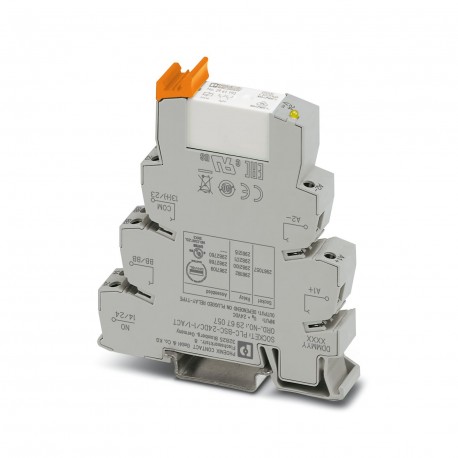
PLC-RSC- 24DC/ 1- 1/ACT 2967109 PHOENIX CONTACT Relay Module
$0.00USD
3861 in stock
Key Specifications
:Freewheeling diode; Freewheeling diode
EMC:B
Color:gray (RAL 7042)
Depth:94 mm
Supplier Information
Products: 0
Usually ships within 2-3 business days
Quality Guaranteed
Fast Shipping
Technical Support
Technical Specifications
| Parameter | Value |
|---|---|
| Freewheeling diode; Freewheeling diode | |
| EMC | B |
| Color | gray (RAL 7042) |
| Depth | 94 mm |
| Width | 14 mm |
| Height | 80 mm |
| Altitude | ≤ 2000 m |
| Humidity | A |
| Enclosure | Required protection according to the Rules shall be provided upon installation on board |
| Vibration | B/C |
| Insulation | Basic insulation |
| Application | Output function |
| Certificate | CE-compliant |
| Temperature | D |
| Product type | Relay Module |
| Screw thread | M3 |
| Assembly note | in rows with zero spacing |
| Mounting type | DIN rail mounting |
| Identification | ISA-S71.04. G3 Harsh Group |
| Operating mode | 100% operating factor |
| Product family | PLC-INTERFACE |
| Test voltage () | 1 kVrms(50 Hz, 1 min.) |
| Article revision | 11 |
| Contact material | AgNi |
| Drive (polarity) | polarized |
| Pollution degree | 2 |
| Stripping length | 8 mm |
| Connection method | Screw connection |
| Mounting position | any |
| Tightening torque | 0.6 Nm ... 0.8 Nm |
| Drive and function | monostable |
| Protective circuit | Reverse polarity protection; Polarity protection diode |
| Switching capacity | 2 A (24 V (DC13)) |
| Input voltage range | 20.2 V DC ... 33.6 V DC (20 °C) |
| Rated surge voltage | 4 kV (Safe isolation, reinforced insulation, and 6 kV between input circuit and output contact current paths) |
| Overvoltage category | III |
| Typical release time | 10 ms |
| Low Voltage Directive | Conformance with Low Voltage Directive |
| Standards/regulations | IEC 61810-1 |
| Typical response time | 8 ms |
| Contact switching type | 2 N/O contacts |
| Maximum inrush current | 25 A (20 ms) |
| Min. switching current | 10 mA (5 V) |
| Type of switch contact | Single contact |
| Mechanical service life | 3x 10⁷cycles |
| Switching capacity min. | 50 mW |
| Nominal input voltage UN | 24 V DC |
| Rated insulation voltage | 250 V AC |
| Maximum switching voltage | 250 V AC/DC (The separating plate PLC-ATP should be installed for voltages larger than 250 V (L1, L2, L3) between identical terminal blocks in adjacent modules. Potential bridging is then carried out with FBST 8-PLC... or ...FBST 500...) |
| Minimum switching voltage | 5 V (10 mA) |
| Operating voltage display | Yellow LED |
| Conductor cross section AWG | 26 ... 14 |
| Limiting continuous current | 6 A |
| Typical input current at UN | 18 mA |
| Date of last data management | 11.07.2024 |
| Degree of protection (Relay) | RT III |
| Conductor cross section rigid | 0.14 mm² ... 2.5 mm² |
| Electromagnetic compatibility | Conformance with EMC directive |
| Input power dissipation for UN | 0.43 W |
| Test voltage (Winding/contact) | 4 kVrms(50 Hz, 1 min.) |
| Ambient temperature (operation) | -40 °C ... 70 °C |
| Conductor cross section flexible | 0.14 mm² ... 2.5 mm² |
| Degree of protection (Relay base) | IP20 |
| Interrupting rating (ohmic load) max. | 144 W (24 V DC) |
| Flammability rating according to UL 94 | V0 (Housing) |
| Ambient temperature (storage/transport) | -40 °C ... 85 °C |
| Test voltage (N/O contact / N/O contact) | 2.5 kVrms(50 Hz, 1 min.) |
| Degree of protection (Installation location) | ≤ IP54 |
| Maximum power dissipation for nominal condition | 0.43 W |
| Nominal voltage (plugged-in electromechanical relay) | 24 V DC |
Product Description
PLC-INTERFACE for output functions, consisting of PLC-BSC.../ACT base terminal block with screw connection and plug-in miniature relay with power contact, for mounting on NS 35/7.5 rail, 2 closing con
Key Features
- Industrial grade quality
- RoHS compliant
- CE certified
- 1-year warranty
Product Documents
Datasheet
Technical specifications and performance data
User Manual
Installation and operation guide


