In Stock Hot Product
MKDS 3/ 8 OG BD:12-19
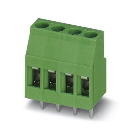
MKDS 3/ 8 OG BD:12-19 1873170 PHOENIX CONTACT PCB terminal block, nominal current: 24 A, nom. voltage: 400 V..
$0.00USD
3491 in stock
Key Specifications
GTIN:4055626183725
Orderkey:1873170
(Drawings):
Packing unit:1
Supplier Information
Products: 0
Usually ships within 2-3 business days
Quality Guaranteed
Fast Shipping
Technical Support
Technical Specifications
| Parameter | Value |
|---|---|
| GTIN | 4055626183725 |
| Orderkey | 1873170 |
| (Drawings) | |
| Packing unit | 1 |
| Pitch (Drawings) | 5 mm |
| ETIM 5.0 (eCl@ss) | EC002643 |
| ETIM 6.0 (eCl@ss) | EC002643 |
| ETIM 7.0 (eCl@ss) | EC002643 |
| UNSPSC 13.2 (ETIM) | 39121432 |
| UNSPSC 18.0 (ETIM) | 39121432 |
| UNSPSC 19.0 (ETIM) | 39121432 |
| UNSPSC 20.0 (ETIM) | 39121432 |
| UNSPSC 21.0 (ETIM) | 39121432 |
| Custom tariff number | 85369010 |
| (Ambient conditions) | Test passed |
| Pin layout (Drawings) | Linear pinning |
| Mounting type (Drawings) | Wave soldering |
| Dry heat (Vibration test) | 168 h/100°C |
| Note (Connection capacity) | WEEE/RoHS-compliant, free of whiskers according to IEC 60068-2-82/JEDEC JESD 201 |
| Humid heat (Vibration test) | 48 h/30 °C/92 % |
| Number of levels (Drawings) | 1 |
| (Standards and Regulations) | For details about hazardous substances go to tab “Downloads”, Category “Manufacturer's declaration” |
| Connection method (Drawings) | Screw connection with tension sleeve |
| Note (Packaging information) | For safe conductor connection, always adhere to a defined tightening torque. Particularly in the case of PCB terminal blocks with two or three positions, the individual solder pin for each contact point cannot compensate for this. That is why the terminal blocks must be supported during conductor connection (held with one hand, support on the housing). |
| Range of articles (Drawings) | MKDS 3 |
| eCl@ss 5.1 (Classifications) | 27261100 |
| eCl@ss 6.0 (Classifications) | 27261100 |
| eCl@ss 7.0 (Classifications) | 27440401 |
| eCl@ss 8.0 (Classifications) | 27440401 |
| eCl@ss 9.0 (Classifications) | 27440401 |
| Rated current (Pull-out test) | 24 A |
| Nom. voltage (Item properties) | 400 V |
| Number of positions (Drawings) | 8 |
| Result (Temperature-rise test) | Test passed |
| Torque (Electrical parameters) | 0.5 Nm ... 0.6 Nm |
| Number of potentials (Drawings) | 8 |
| Pitch (Material data - housing) | 5 mm |
| Rated voltage (Item properties) | 250 V |
| Number of connections (Drawings) | 8 |
| Specification (Electrical tests) | IEC 60947-1:2007-06 + A1:2010-12 + A2:2014-09 |
| Amplitude (Temperature-rise test) | 0.35 mm (10 - 60.1 Hz) |
| Caption (Material data - housing) | Schematic representation – for additional information, see product range drawing in the Download Center |
| Frequency (Temperature-rise test) | 10 - 150 - 10 Hz |
| Nominal current (Item properties) | 24 A |
| pluggable (Electrical parameters) | Yes |
| Sweep speed (Temperature-rise test) | 1 octave/min |
| (Termination and connection method) | 2.5 mm² / flexible / > 50 N |
| Acceleration (Temperature-rise test) | 5 g (60.1 - 150 Hz) |
| Brief article description (Drawings) | PCB terminal block |
| Connection test (Ambient conditions) | IEC 60998-2-2:2002-12 |
| Type of note (Packaging information) | Note on application |
| Pin spacing (Material data - housing) | 5 mm |
| Rated voltage (III/2) (Pull-out test) | 400 V |
| Specification (Temperature-rise test) | IEC 60068-2-6:1995-03 |
| China RoHS (Standards and Regulations) | Environmentally Friendly Use Period = 50 years |
| Contact material (Connection capacity) | Cu alloy |
| REACh SVHC (Standards and Regulations) | Lead 7439-92-1 |
| Rated voltage (II/2) (Item properties) | 630 V |
| Conductor cross section (Pull-out test) | 2.5 mm² |
| Housing color (Material data - contact) | orange (2003) |
| Rated voltage (III/2) (Item properties) | 400 V |
| Pin dimensions (Material data - housing) | 0.9 x 0.9 mm |
| Pin spacing (Dimensions for the product) | 5 mm |
| Solder pin [P] (Material data - housing) | 5 mm |
| Stripping length (Electrical parameters) | 8 mm |
| Connection method (Electrical parameters) | Screw connection with tension sleeve |
| Hole diameter (Dimensions for the product) | 1.3 mm |
| Rated surge voltage (III/2) (Pull-out test) | 4 kV |
| Rated surge voltage (II/2) (Item properties) | 4 kV |
| Dimensional drawing (Material data - housing) | |
| Insulating material (Material data - contact) | PA |
| Rated surge voltage (III/2) (Item properties) | 4 kV |
| Rated surge voltage (III/3) (Item properties) | 4 kV |
| Surface characteristics (Connection capacity) | Tin-plated |
| Type of packaging (Dimensions for PCB design) | packed in cardboard |
| Pieces per package (Dimensions for PCB design) | 50 |
| Result (Air clearances and creepage distances) | Test passed |
| Test duration per axis (Temperature-rise test) | 2.5 h |
| Pull-out test (Termination and connection method) | IEC 60998-2-1:2002-12 |
| Insulating material group (Material data - contact) | I |
| Note on connection cross section (Electrical tests) | With connected conductor 4 mm² (solid). |
| CTI according to IEC 60112 (Material data - contact) | 600 |
| Clearances and creepage distances (Electrical tests) | IEC 60947-1:2007-06 + A1:2010-12 + A2:2014-09 |
| Conductor cross section solid (Electrical parameters) | 0.2 mm² ... 4 mm² |
| Specification (Air clearances and creepage distances) | IEC 60998-1:2002-12 |
| Denomination packing units (Dimensions for PCB design) | Pcs. |
| Conductor cross section flexible (Electrical parameters) | 0.2 mm² ... 2.5 mm² |
| Minimum creepage distance value (II/2) (Electrical tests) | 3.2 mm |
| Minimum creepage distance value (III/2) (Electrical tests) | 3 mm |
| Minimum creepage distance value (III/3) (Electrical tests) | 3.2 mm |
| Conductor cross section AWG / kcmil (Electrical parameters) | 24 ... 12 |
| Ambient temperature (assembly) (General product information) | -5 °C ... 100 °C |
| Ambient temperature (operation) (General product information) | -40 °C ... 100 °C (Depending on the current carrying capacity/derating curve) |
| Test for conductor damage and slackening (Ambient conditions) | IEC 60998-2-1:2002-12 |
| Metal surface soldering area (top layer) (Connection capacity) | Tin (4 - 8 µm Sn) |
| Metal surface terminal point (top layer) (Connection capacity) | Tin (4 - 8 µm Sn) |
| Flammability rating according to UL 94 (Material data - contact) | V0 |
| Minimum clearance - inhomogeneous field (II/2) (Electrical tests) | 3 mm |
| Minimum clearance - inhomogeneous field (III/2) (Electrical tests) | 3 mm |
| Minimum clearance - inhomogeneous field (III/3) (Electrical tests) | 3 mm |
| 2 conductors with same cross section, solid (Electrical parameters) | 0.2 mm² ... 1.5 mm² |
| Ambient temperature (storage/transport) (General product information) | -40 °C ... 70 °C |
| 2 conductors with same cross section, flexible (Electrical parameters) | 0.2 mm² ... 1.5 mm² |
| Glow wire flammability index GWFI according to EN 60695-2-12 (Material data - contact) | 850 |
| Glow wire ignition temperature GWIT according to EN 60695-2-13 (Material data - contact) | 775 |
| Conductor cross section / conductor type / tensile force (Termination and connection method) | 0.2 mm² / solid / > 10 N |
| Conductor cross section, flexible, with ferrule, with plastic sleeve (Electrical parameters) | 0.25 mm² ... 2.5 mm² |
| Temperature for the ball pressure test according to EN 60695-10-2 (Material data - contact) | 125 °C |
| Conductor cross section flexible, with ferrule without plastic sleeve (Electrical parameters) | 0.25 mm² ... 2.5 mm² |
| Flammability rating according to UL 94 (Resistance to ageing, humidity and penetration of solids) | V0 |
| 2 conductors with same cross section, flexible, with ferrule without plastic sleeve (Electrical parameters) | 0.25 mm² ... 0.75 mm² |
| 2 conductors with the same cross section, flexible, with TWIN ferrule with plastic sleeve (Electrical parameters) | 0.5 mm² ... 1.5 mm² |
Product Description
PCB terminal block, nominal current: 24 A, rated voltage (III/2): 400 V, nominal cross section: 2.5 mm², pitch: 5 mm, number of positions: 8, connection method: Screw connection with tension sleeve, m
Key Features
- Industrial grade quality
- RoHS compliant
- CE certified
- 1-year warranty
Technical Details
DiagramType: MKDS 3/2 and MKDS 3/3Test following DIN EN 60512-5-2:2003-01Reduction factor = 1No. of positions: 5
Product Documents
Datasheet
Technical specifications and performance data
User Manual
Installation and operation guide


