In Stock Hot Product
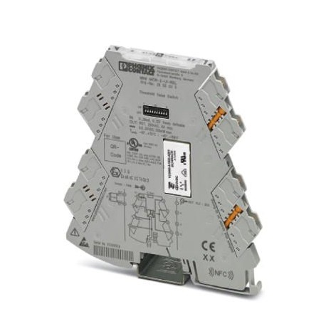
MINI MCR-2-UI-REL
MINI MCR-2-UI-REL 2902033 PHOENIX CONTACT Limit value switches
$0.00USD
3429 in stock
Key Specifications
GTIN:4046356652056
Orderkey:2902033
(General):Class I, Zone 2, Group IIC T4A
Catalog page:Page 91 (C-5-2017)
Supplier Information
Products: 0
Usually ships within 2-3 business days
Quality Guaranteed
Fast Shipping
Technical Support
Technical Specifications
| Parameter | Value |
|---|---|
| GTIN | 4046356652056 |
| Orderkey | 2902033 |
| (General) | Class I, Zone 2, Group IIC T4A |
| Catalog page | Page 91 (C-5-2017) |
| Depth (Note) | 120.5 mm |
| Packing unit | 1 pc |
| Width (Note) | 6.2 mm |
| (Input data) | 240 V AC (UL) |
| Height (Note) | 110.5 mm |
| ATEX (General) | II 3 G Ex nA nC IIC T4 Gc X |
| Country of origin | DE (Germany) |
| (Connection data) | Class I, Zone 2, Group IIC T4A |
| (Switching output) | 20 mA (24 V DC) |
| Custom tariff number | 85437090 |
| DNV GL-EMC (General) | A |
| (Ambient conditions) | 0 mA ... 24 mA (can be set via software) |
| Conformance (General) | CE-compliant |
| ATEX (Connection data) | II 3 G Ex nA nC IIC T4 Gc X |
| Color (Connection data) | gray |
| Noise emission (General) | EN 61000-6-4 |
| Output name (Input data) | Relay output |
| UL, USA/Canada (General) | UL 508 Listed |
| Contact type (Input data) | 1 PDT |
| DNV GL-Humidity (General) | B |
| DNV GL-Enclosure (General) | Required protection according to the Rules shall be provided upon installation on board |
| DNV GL-Vibration (General) | A |
| Screw thread (Power supply) | M3 |
| (Standards and Regulations) | For details about hazardous substances go to tab “Downloads”, Category “Manufacturer's declaration” |
| DNV GL-Temperature (General) | B |
| Conformance (Connection data) | CE-compliant |
| Contact material (Input data) | AgSnO2, hard gold-plated |
| Electrical isolation (General) | Reinforced insulation in accordance with IEC 61010-1 |
| Stripping length (Power supply) | 10 mm |
| Connection method (Power supply) | Screw connection |
| Internal hysteresis (Input data) | can be set freely via software |
| Noise emission (Connection data) | EN 61000-6-4 |
| Noise immunity (Connection data) | EN 61000-6-2 When being exposed to interference, there may be minimal deviations. |
| Status display (Connection data) | Yellow LED (switching output) |
| UL, USA/Canada (Connection data) | UL 508 Listed |
| No. of channels (Connection data) | 1 |
| Housing material (Connection data) | PBT |
| Max. switching current (Input data) | 6 A (for 250 V AC) |
| Min. switching current (Input data) | 100 mA (12 V DC) |
| Mounting position (Connection data) | any |
| Mechanical service life (Input data) | 2x 10⁷cycles |
| Power consumption (Switching output) | ≤ 0.5 W |
| Weight per Piece (excluding packing) | 128.800 g |
| Degree of pollution (Connection data) | 2 |
| China RoHS (Standards and Regulations) | Environmentally Friendly Use Period = 50 |
| Electrical isolation (Connection data) | Reinforced insulation in accordance with IEC 61010-1 |
| Maximum switching voltage (Input data) | 250 V AC |
| Overvoltage category (Connection data) | II |
| REACh SVHC (Standards and Regulations) | Lead 7439-92-1 |
| Assembly instructions (Connection data) | The T connector can be used to bridge the supply voltage. It can be snapped onto a 35 mm DIN rail according to EN 60715. |
| Electromagnetic compatibility (General) | Conformance with EMC directive |
| Max. input current (Ambient conditions) | 24 mA |
| Supply voltage range (Switching output) | 9.6 V DC ... 30 V DC (The DIN rail bus connector (ME 6,2 TBUS-2 1,5/5-ST-3,81 GN, Order No. 2869728) can be used to bridge the supply voltage. It can be snapped onto a 35 mm DIN rail according to EN 60715)) |
| max. input voltage (Ambient conditions) | 12 V |
| Limiting continuous current (Input data) | 6 A |
| Current input signal (Ambient conditions) | 0 mA ... 20 mA (via DIP switch) |
| Nominal supply voltage (Switching output) | 24 V DC |
| Voltage input signal (Ambient conditions) | 0 V ... 10 V (via DIP switch) |
| Rated insulation voltage (Connection data) | 300 V (effective) |
| Switching point accuracy (Connection data) | < 0.1 % |
| Ambient temperature (operation) (Dimensions) | -40 °C ... 70 °C |
| Maximum transmission error (Connection data) | 0.1 % (of final value) |
| Utilization restriction (Key Commercial Data) | 1 |
| Configurable/programmable (Ambient conditions) | Yes |
| Typical current consumption (Switching output) | 40 mA (12 V DC) |
| Electromagnetic compatibility (Connection data) | Conformance with EMC directive |
| Setting range of the response delay (Input data) | 0 s ... 10 s (can be set freely via software) |
| Maximum temperature coefficient (Connection data) | 0.01 %/K |
| Input resistance current input (Ambient conditions) | approx. 50 Ω (+ 0.7 V for test diode) |
| Test voltage, input/output/supply (Connection data) | 3 kV (50 Hz, 1 min.) |
| Ambient temperature (storage/transport) (Dimensions) | -40 °C ... 85 °C |
| Conductor cross section flexible max. (Power supply) | 1.5 mm² |
| Conductor cross section flexible min. (Power supply) | 0.2 mm² |
| Input resistance of voltage input (Ambient conditions) | > 120 kΩ |
| Max. AWG conductor cross section, flexible (Power supply) | 12 |
| Min. AWG conductor cross section, flexible (Power supply) | 24 |
| Fire protection for rail vehicles (DIN EN 45545-2) R22 (General) | HL 1 - HL 2 |
| Fire protection for rail vehicles (DIN EN 45545-2) R23 (General) | HL 1 - HL 2 |
| Fire protection for rail vehicles (DIN EN 45545-2) R24 (General) | HL 1 - HL 2 |
| Fire protection for rail vehicles (DIN EN 45545-2) R22 (Connection data) | HL 1 - HL 2 |
| Fire protection for rail vehicles (DIN EN 45545-2) R23 (Connection data) | HL 1 - HL 2 |
| Fire protection for rail vehicles (DIN EN 45545-2) R24 (Connection data) | HL 1 - HL 2 |
| Single conductor/terminal point, solid, with ferrule, max. (Power supply) | 1.5 mm² |
| Single conductor/terminal point, solid, with ferrule, min. (Power supply) | 0.2 mm² |
| Single conductor/terminal point, solid, without ferrule, max. (Power supply) | 2.5 mm² |
| Single conductor/terminal point, solid, without ferrule, min. (Power supply) | 0.2 mm² |
Product Description
Universally configured limit value switch with switching relay output and plug-in connection technology for switching analog limit values. Configurable via DIP switch or software. Screw connection tec
Key Features
- Industrial grade quality
- RoHS compliant
- CE certified
- 1-year warranty
Product Documents
Datasheet
Technical specifications and performance data
User Manual
Installation and operation guide


