In Stock Hot Product
MC 1,5/ 5-ST-5,08
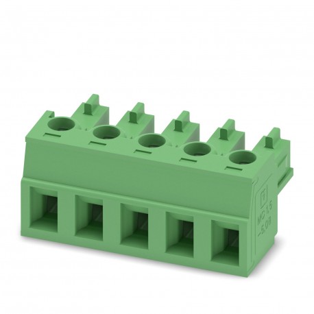
MC 1,5/ 5-ST-5,08 1836105 PHOENIX CONTACT Printed-circuit board connector
$0.00USD
4714 in stock
Key Specifications
:0.2 mm² / flexible / > 10 N
Note:WEEE/RoHS-compliant, free of whiskers according to IEC 60068-2-82/JEDEC JESD 201
Type:Standard
Pitch:5.08 mm
Supplier Information
Products: 0
Usually ships within 2-3 business days
Quality Guaranteed
Fast Shipping
Technical Support
Technical Specifications
| Parameter | Value |
|---|---|
| 0.2 mm² / flexible / > 10 N | |
| Note | WEEE/RoHS-compliant, free of whiskers according to IEC 60068-2-82/JEDEC JESD 201 |
| Type | Standard |
| Pitch | 5.08 mm |
| Result | Test passed |
| Amplitude | 0.35 mm (10 Hz ... 60.1 Hz) |
| Frequency | 10 - 150 - 10 Hz |
| Width [w] | 25.4 mm |
| Height [h] | 11.1 mm |
| Length [l] | 15.5 mm |
| Sweep speed | 1 octave/min |
| Acceleration | 5g (60.1 Hz ... 150 Hz) |
| Locking type | without |
| Product line | COMBICON Connectors S |
| Product type | PCB connector |
| No. of cycles | 25 |
| Specification | IEC 60999-1:1999-11 |
| Number of rows | 1 |
| Product family | MC 1,5/..-ST |
| Thermal stress | 100 °C/168 h |
| Color (Housing) | green (6021) |
| Mounting flange | without |
| Test directions | X-, Y- and Z-axis |
| Article revision | 06 |
| Connector system | COMBICON MC 1,5 |
| Contact material | Cu alloy |
| Corrosive stress | 0.2 dm3SO2on 300 dm3/40 °C/1 cycle |
| Stripping length | 7 mm |
| Connection method | Screw connection with tension sleeve |
| Tightening torque | 0.22 Nm ... 0.25 Nm |
| Type of packaging | packed in cardboard |
| Contact resistance | 1.2 mΩ |
| Nominal current IN | 8 A |
| Nominal voltage UN | 320 V |
| Notes on operation | In accordance with IEC 61984, COMBICON connectors have no switching power (COC). During designated use, they must not be plugged in or disconnected when carrying voltage or under load. |
| Dimensional drawing | |
| Insulating material | PA |
| Number of positions | 5 |
| Number of potentials | 5 |
| Rated voltage (II/2) | 630 V |
| Contact resistance R1 | 1.2 mΩ |
| Contact resistance R2 | 1.4 mΩ |
| Drive form screw head | Slotted (L) |
| Nominal cross section | 1.5 mm² |
| Number of connections | 5 |
| Rated voltage (III/2) | 320 V |
| Rated voltage (III/3) | 250 V |
| Test duration per axis | 2.5 h |
| Contact connection type | Socket |
| Surface characteristics | hot-dip tin-plated |
| Insulating material group | I |
| recommended crimping tool | 1212034 CRIMPFOX 6 |
| CTI according to IEC 60112 | 600 |
| Rated surge voltage (II/2) | 4 kV |
| Tested number of positions | 12 |
| Conductor cross section AWG | 28 ... 16 |
| Insertion/withdrawal cycles | 25 |
| Rated surge voltage (III/2) | 4 kV |
| Rated surge voltage (III/3) | 4 kV |
| Conductor cross section rigid | 0.14 mm² ... 1.5 mm² |
| Ambient temperature (assembly) | -5 °C ... 100 °C |
| Ambient temperature (operation) | -40 °C ... 100 °C (dependent on the derating curve) |
| Rated insulation voltage (II/2) | 630 V |
| Conductor cross section flexible | 0.14 mm² ... 1.5 mm² |
| Note on connection cross section | With connected conductor 1.5 mm² (solid). |
| Rated insulation voltage (III/2) | 320 V |
| Rated insulation voltage (III/3) | 250 V |
| minimum creepage distance (II/2) | 3.2 mm |
| Power-frequency withstand voltage | 2.21 kV |
| minimum creepage distance (III/2) | 3 mm |
| minimum creepage distance (III/3) | 3.2 mm |
| Conductor/PCB connection direction | 0 ° |
| Cylindrical gauge a x b / diameter | 2.4 mm x 1.5 mm / 1.6 mm |
| Withdraw strength per pos. approx. | 5 N |
| Insertion strength per pos. approx. | 8 N |
| Relative humidity (storage/transport) | 30 % ... 70 % |
| Flammability rating according to UL 94 | V0 |
| Impulse withstand voltage at sea level | 4.8 kV |
| Metal surface contact area (top layer) | Tin (4 - 8 µm Sn) |
| Ambient temperature (storage/transport) | -40 °C ... 70 °C |
| Comparative tracking index (IEC 60112) | CTI 600 |
| Metal surface terminal point (top layer) | Tin (4 - 8 µm Sn) |
| 2 conductors with same cross section, solid | 0.08 mm² ... 0.5 mm² |
| Insulation resistance, neighboring positions | > 5 MΩ |
| 2 conductors with same cross section, flexible | 0.08 mm² ... 0.75 mm² |
| minimum clearance value - non-homogenous field (II/2) | 3 mm |
| minimum clearance value - non-homogenous field (III/2) | 3 mm |
| minimum clearance value - non-homogenous field (III/3) | 3 mm |
| Glow wire flammability index GWFI according to EN 60695-2-12 | 850 |
| Glow wire ignition temperature GWIT according to EN 60695-2-13 | 775 |
| Temperature for the ball pressure test according to EN 60695-10-2 | 125 °C |
| Conductor cross section, flexible, with ferrule, with plastic sleeve | 0.25 mm² ... 0.5 mm² |
| Conductor cross section flexible, with ferrule without plastic sleeve | 0.25 mm² ... 1.5 mm² |
| Conductor cross section/conductor type/tractive force setpoint/actual value | 0.2 mm² / solid / > 10 N |
| 2 conductors with same cross section, flexible, with ferrule without plastic sleeve | 0.25 mm² ... 0.34 mm² |
| 2 conductors with the same cross section, flexible, with TWIN ferrule with plastic sleeve | 0.5 mm² ... 0.5 mm² |
Product Description
Connector for printed circuit board, nominal section: 1.5 mm², color: green, nominal current: 8 A, nominal voltage (III/2): 320 V, contact surface: Tin, contact type: Female, number of potentials: 5,
Key Features
- Industrial grade quality
- RoHS compliant
- CE certified
- 1-year warranty
Product Documents
Datasheet
Technical specifications and performance data
User Manual
Installation and operation guide


