In Stock Hot Product
MACX MCR-EX-SL-RPSSI-I-SP
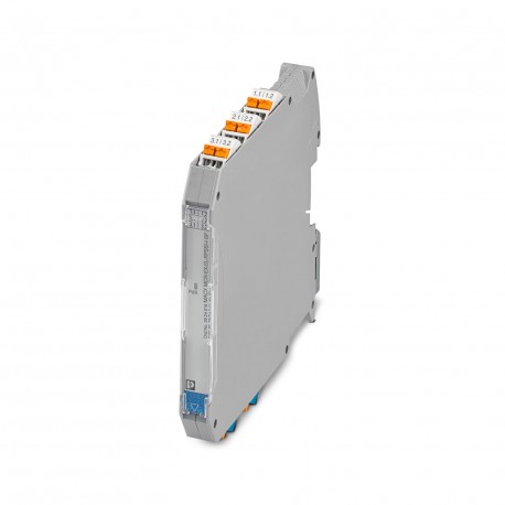
MACX MCR-EX-SL-RPSSI-I-SP 2924016 PHOENIX CONTACT Power/input isolating amplifier
$0.00USD
3987 in stock
Key Specifications
:< 600 µs (for jump 0 mA ... 20 mA, load 600 Ω)
EMC:A
Note:and EN 61326
Type:Ex i signal conditioners with SIL functional safety
Supplier Information
Products: 0
Usually ships within 2-3 business days
Quality Guaranteed
Fast Shipping
Technical Support
Technical Specifications
| Parameter | Value |
|---|---|
| < 600 µs (for jump 0 mA ... 20 mA, load 600 Ω) | |
| EMC | A |
| Note | and EN 61326 |
| Type | Ex i signal conditioners with SIL functional safety |
| Color | gray (RAL 7042) |
| Depth | 113.7 mm |
| Width | 12.5 mm |
| Height | 107.9 mm |
| Altitude | ≤ 2000 m (The technical data refers to altitudes ≤2000 m above mean sea level. For altitudes >2000 m above mean sea level, refer to the data sheet.) |
| Humidity | B |
| Enclosure | Required protection according to the Rules shall be provided upon installation on board |
| Vibration | A |
| Insulation | Safe isolation |
| Application | Analog IN |
| Certificate | CE-compliant |
| Designation | Repeater power supply operation |
| Temperature | B |
| Height range | > 2000 m ... 3000 m |
| Input signal | Current |
| Product type | Repeater power supply |
| Test voltage | 2.5 kV AC (50 Hz, 60 s) |
| Voltage drop | < 3.5 V (in input isolating amplifier operation) |
| HART function | Yes |
| Mounting type | DIN rail mounting |
| Output ripple | < 20 mVrms |
| Identification | II (1) G [Ex ia Ga] IIC |
| Noise emission | EN 61000-6-4 |
| Noise immunity | EN 61000-6-2 |
| Product family | MACX Analog |
| Status display | Green LED (supply voltage) |
| No. of channels | 1 |
| Article revision | 15 |
| Depth NS 35/7,5 | 114.5 mm (Snapped onto DIN rail NS 35/7,5 in accordance with EN 60715) |
| Housing material | PA 6.6-FR |
| Input current Ii | ≤ 150 mA |
| Input voltage Ui | ≤ 30 V |
| Number of inputs | 1 |
| Pollution degree | 2 |
| Stripping length | 10 mm |
| Connection method | Push-in connection |
| Number of outputs | 1 |
| Power consumption | < 1.8 W (20 mA / 1000 Ω) |
| Power dissipation | < 1.1 W (24 V DC / 20 mA / 1000 Ω) |
| Current limitation | 25 mA |
| Output description | Current output (active and passive) |
| Dimensional drawing | |
| Ex i circuits (EPL) | Ga |
| Protocols supported | HART-transparent |
| Current input signal | 4 mA ... 20 mA |
| Degree of protection | IP20 (not assessed by UL) |
| Electrical isolation | 3-way isolation |
| Max. output power Po | 587 mW |
| Overvoltage category | II |
| Supply voltage range | 19.2 V DC ... 30 V DC |
| Current output signal | 4 mA ... 20 mA (active) |
| Ex installation (EPL) | Gc |
| Standards/regulations | IEC/EN 61010-1 |
| Max. output current Io | 93 mA |
| Max. output voltage Uo | 25.2 V |
| Nominal supply voltage | 24 V DC -20 % ... +25 % |
| Step response (10-90%) | < 200 µs (for jump 4 mA ... 20 mA, load 600 Ω) |
| Description of the input | Active current input, intrinsically safe |
| Max. current consumption | < 76 mA (24 V DC / 20 mA / 1000 Ω) |
| Rated insulation voltage | 300 Vrms |
| Maximum transmission error | < 0.1 % (of final value 20 mA) |
| Transmitter supply voltage | > 16 V (20 mA) |
| Conductor cross section AWG | 24 ... 14 |
| Max. internal inductance Li | negligible |
| Reverse polarity protection | yes |
| Transmission error, typical | < 0.05 % (of final value 20 mA) |
| Max. internal capacitance Ci | negligible |
| Signal transmission behavior | In = Out |
| Conductor cross section rigid | 0.2 mm² ... 2.5 mm² |
| Electromagnetic compatibility | Conformance with EMC directive |
| Ambient temperature (operation) | -40 °C ... 60 °C (Any mounting position) |
| Load/output load current output | < 1000 Ω (20 mA) |
| Maximum temperature coefficient | < 0.01 %/K |
| Underload/overload signal range | 0 mA ... 24 mA (Extended transmission range for diagnostics) |
| Conductor cross section flexible | 0.2 mm² ... 2.5 mm² |
| Permissible humidity (operation) | 10 % ... 95 % (non-condensing) |
| Temperature coefficient, typical | < 0.004 %/K |
| Polarization and surge protection | Yes |
| Safety-related maximum voltage Um | 253 V AC |
| Flammability rating according to UL 94 | V0 (Housing) |
| Ambient temperature (storage/transport) | -40 °C ... 80 °C |
| Output behavior in the event of an error | 0 mA (Cable break in the input) |
| Electrical isolation between input and output | yes |
| Typical deviation from the measuring range final value | 1 % |
| Conductor cross section flexible (2 conductors with same cross section) | 0.25 mm² ... 0.34 mm² (TWIN ferrule without plastic sleeve) |
| I (mixed circuit): Max. external inductivity Lo/ Max. external capacitance Co | 37 mH / 0.54 µF, 0.35 mH / 1 µF, 0.009 mH / 2.9 µF, 0.001 mH / 4.15 µF |
| I (simple circuit): Max. external inductivity Lo/ Max. external capacitance Co | 40 mH / 4.8 µF |
| IIA (mixed circuit): Max. external inductivity Lo/ Max. external capacitance Co | 26 mH / 470 nF, 20 mH / 570 nF, 1 mH / 630 nF, 0.5 mH / 720 nF, 0.1 mH / 1.1 µF, 0.005 mH / 2.9 µF |
| IIC (mixed circuit): Max. external inductivity Lo/ Max. external capacitance Co | 2.2 mH / 47 nF, 2 mH / 49 nF, 1 mH / 63 nF, 500 µH / 80 nF, 200 µH / 107 nF |
| IIA (simple circuit): Max. external inductivity Lo/ Max. external capacitance Co | 26 mH / 2.9 µF |
| IIB (simple circuit): Max. external inductivity Lo/ Max. external capacitance Co | 14 mH / 820 nF |
| IIC (simple circuit): Max. external inductivity Lo/ Max. external capacitance Co | 3 mH / 107 nF |
| IIB/III (mixed circuit): Max. external inductivity Lo/ Max. external capacitance Co | 16 mH / 370 nF, 500 µH / 510 nF, 200 µH / 660 nF, 100 µH / 820 nF |
Product Description
Intrinsically safe input and power signal conditioner with HART transparency. It transmits 0/4-20 mA powered or active signals from the Ex zone at a load (active or passive) to the safe zone. 3-way ga
Key Features
- Industrial grade quality
- RoHS compliant
- CE certified
- 1-year warranty
Product Documents
Datasheet
Technical specifications and performance data
User Manual
Installation and operation guide


