In Stock Hot Product
IB IL TEMP 2 UTH-PAC
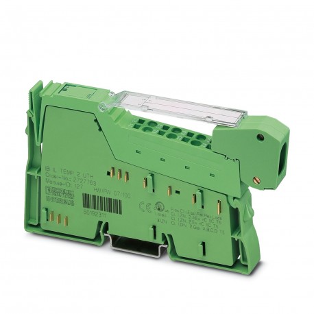
IB IL TEMP 2 UTH-PAC 2861386 PHOENIX CONTACT Inline terminal
$0.00USD
3005 in stock
Key Specifications
:Failure of or insufficient communications power ULI/O error message sent to the bus coupler
Type:modular
Depth:71.5 mm
Width:12.2 mm
Supplier Information
Products: 0
Usually ships within 2-3 business days
Quality Guaranteed
Fast Shipping
Technical Support
Technical Specifications
| Parameter | Value |
|---|---|
| Failure of or insufficient communications power ULI/O error message sent to the bus coupler | |
| Type | modular |
| Depth | 71.5 mm |
| Width | 12.2 mm |
| Height | 136.8 mm |
| CCCex note | Use in potentially explosive areas is not permitted in China. |
| Input name | Analog UTH inputs |
| Current draw | max. 60 mA |
| Product type | I/O component |
| ID code (hex) | 7F |
| Mounting type | DIN rail mounting |
| ID code (dec.) | 127 |
| Operating mode | Process data operation with 2 words |
| Product family | Inline |
| Supply voltage | 7.5 V DC (via voltage jumper) |
| Connection name | Inline connector |
| Register length | 32 bit |
| Article revision | 11 |
| Number of inputs | 2 (Thermocouples or linear voltage) |
| Pollution degree | 2 (IEC 60664-1, EN 60664-1) |
| Protection class | III (IEC 61140, EN 61140, VDE 0140-1) |
| Stripping length | 8 mm |
| Connection method | Inline data jumper |
| Length code (dec) | 02 |
| Length code (hex) | 02 |
| Scope of delivery | including Inline connector and labeling field |
| Input address area | 4 Byte |
| Note on dimensions | Housing dimensions |
| Protective circuit | Surge protection (TC channels); up to ±40 V |
| Transmission speed | 500 kbps |
| A/D conversion time | typ. 120 µs (per channel) |
| Dimensional drawing | |
| Measuring principle | Successive approximation |
| Note on application | Only for industrial use |
| Output address area | 4 Byte |
| Process data update | max. 30 ms (For both channels) |
| Degree of protection | IP20 |
| Diagnostics messages | Failure of the internal I/O supply I/O error message sent to the bus coupler |
| Number of interfaces | 2 |
| Overvoltage category | II (IEC 60664-1, EN 60664-1) |
| Process data channel | 32 bit |
| Supply voltage range | 19.2 V DC ... 30 V DC (including all tolerances, including ripple) |
| Connection technology | 2-conductor |
| Required parameter data | 6 Byte |
| Air pressure (operation) | 70 kPa ... 106 kPa (up to 3000 m above sea level) |
| Description of the input | Inputs for thermocouples or linear voltage |
| Conductor cross section AWG | 28 ... 16 |
| Required configuration data | 4 Byte |
| Conductor cross section rigid | 0.08 mm² ... 1.5 mm² |
| Measured value representation | 16 bits (15 bits + sign bit) |
| Conductor cross section, rigid | 0.08 mm² ... 1.5 mm² |
| Ambient temperature (operation) | -25 °C ... 55 °C |
| Air pressure (storage/transport) | 70 kPa ... 106 kPa (up to 3000 m above sea level) |
| Conductor cross section flexible | 0.08 mm² ... 1.5 mm² |
| Permissible humidity (operation) | 10 % ... 95 % (non-condensing) |
| Conductor cross section, flexible | 0.08 mm² ... 1.5 mm² |
| Sensor types that can be used (TC) | U, T, L, J, E, K, N, S, R, B, C, W, HK |
| Ambient temperature (storage/transport) | -25 °C ... 85 °C |
| Note regarding the connection technology | Shielded compensating line for TC with encapsulated sensors |
| Permissible humidity (storage/transport) | 10 % ... 95 % (non-condensing) |
| Maximum power dissipation for nominal condition | 0.9 W |
| Test voltage: 7.5 V supply (bus logic)/functional ground | 500 V AC, 50 Hz, 1 min. |
| Test voltage: 24 V analog supply (analog I/O)/functional ground | 500 V AC, 50 Hz, 1 min. |
| Test voltage: 7.5 V supply (bus logics)/24 V analog supply (analog I/O) | 500 V AC, 50 Hz, 1 min. |
Product Description
Inline, Temperature recording module, Analogue UTH inputs: 2 (Thermocouples or linear voltage), connection technology: 2 conductors, transmission rate on local bus: 500 kBit/s, protection rating: IP20
Key Features
- Industrial grade quality
- RoHS compliant
- CE certified
- 1-year warranty
Product Documents
Datasheet
Technical specifications and performance data
User Manual
Installation and operation guide


