In Stock Hot Product
IB IL CNT-PAC
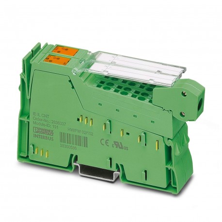
IB IL CNT-PAC 2861852 PHOENIX CONTACT Inline function terminal
$0.00USD
3347 in stock
Key Specifications
:30 V DC (maximum)
Type:modular
Depth:71.5 mm
Width:24.4 mm
Supplier Information
Products: 0
Usually ships within 2-3 business days
Quality Guaranteed
Fast Shipping
Technical Support
Technical Specifications
| Parameter | Value |
|---|---|
| 30 V DC (maximum) | |
| Type | modular |
| Depth | 71.5 mm |
| Width | 24.4 mm |
| Height | 135 mm |
| Input name | Counter input for 24 V signals |
| Designation | Power supply for sensors |
| Output name | Switching output |
| Current draw | max. 50 mA |
| Product type | I/O component |
| ID code (hex) | BF |
| Input current | typ. 5 mA |
| Input voltage | 24 V DC (Nominal voltage) |
| Mounting type | DIN rail mounting |
| ID code (dec.) | 191 |
| Operating mode | Event counting, frequency/time measurement |
| Output current | max. 0.5 A (Nominal current) |
| Output voltage | 24 V DC (Nominal voltage) |
| Product family | Inline |
| Supply voltage | 7.5 V DC (via voltage jumper) |
| Connection name | Inline connector |
| Input frequency | max. 100 kHz |
| Register length | 4 Byte |
| Article revision | 08 |
| Input resistance | approx. 5.7 kΩ |
| Number of inputs | 1 (only one counter input can be used, either for 24 V or for 5 V signals) |
| Protection class | III (IEC 61140, EN 61140, VDE 0140-1) |
| Stripping length | 8 mm |
| Connection method | Inline data jumper |
| Length code (dec) | 02 |
| Length code (hex) | 02 |
| Number of outputs | 1 |
| Scope of delivery | including Inline connectors and marking fields |
| Input address area | 4 Byte |
| Nominal load, lamp | max. 12 W |
| Protective circuit | Short-circuit protection; Yes, short-circuit-proof (automatically switched on again) |
| Transmission speed | 500 kbps |
| Dimensional drawing | |
| Nominal load, ohmic | max. 12 W (48 Ω) |
| Note on application | Only for industrial use |
| Output address area | 4 Byte |
| Degree of protection | IP20 |
| Diagnostics messages | Sensor supply short-circuit |
| Number of interfaces | 2 |
| Process data channel | 32 bit |
| Transmission physics | Copper |
| Connection technology | 2-, 3-conductor |
| Overcurrent shut-down | min. 0.7 A |
| Nominal load, inductive | max. 12 VA (1.2 H, 48 Ω) |
| Required parameter data | 1 Byte |
| Air pressure (operation) | 70 kPa ... 106 kPa (up to 3000 m above sea level) |
| Conductor cross section AWG | 28 ... 16 |
| Required configuration data | 5 Byte |
| Conductor cross section rigid | 0.08 mm² ... 1.5 mm² |
| Conductor cross section, rigid | 0.08 mm² ... 1.5 mm² |
| Input voltage range "0" signal | 0 V DC ... 5 V DC |
| Input voltage range "1" signal | 15 V DC ... 30 V DC |
| Ambient temperature (operation) | -25 °C ... 55 °C |
| Air pressure (storage/transport) | 70 kPa ... 106 kPa (up to 3000 m above sea level) |
| Behavior with inductive overload | Output can be destroyed |
| Conductor cross section flexible | 0.08 mm² ... 1.5 mm² |
| Permissible humidity (operation) | 10 % ... 95 % (non-condensing) |
| Conductor cross section, flexible | 0.08 mm² ... 1.5 mm² |
| Behavior in the event of lamp overload | Auto restart after eliminating the overload |
| Ambient temperature (storage/transport) | -25 °C ... 85 °C |
| Behavior in the event of ohmic overload | Auto restart after eliminating the overload |
| Permissible humidity (storage/transport) | 10 % ... 95 % (non-condensing) |
| Reverse voltage resistance to short pulses | Reverse voltage proof |
| Maximum power dissipation for nominal condition | 1.2 W |
| Test voltage: 24 V supply (I/O) / functional ground | 500 V AC, 50 Hz, 1 min. |
| Test voltage: 7.5 V supply (bus logics)/24 V supply (I/O) | 500 V AC, 50 Hz, 1 min. |
| Test voltage: 7.5 V supply (bus logic)/functional ground | 500 V AC, 50 Hz, 1 min. |
Product Description
Inline counter terminal block, complete with accessories (connectors and marking surfaces), 1 meter input, 1 control input, 1 output, 24 V DC, 500 mA, 3-conductor connection technology
Key Features
- Industrial grade quality
- RoHS compliant
- CE certified
- 1-year warranty
Product Documents
Datasheet
Technical specifications and performance data
User Manual
Installation and operation guide


