In Stock Hot Product
IB IL 24 LSKIP-PAC
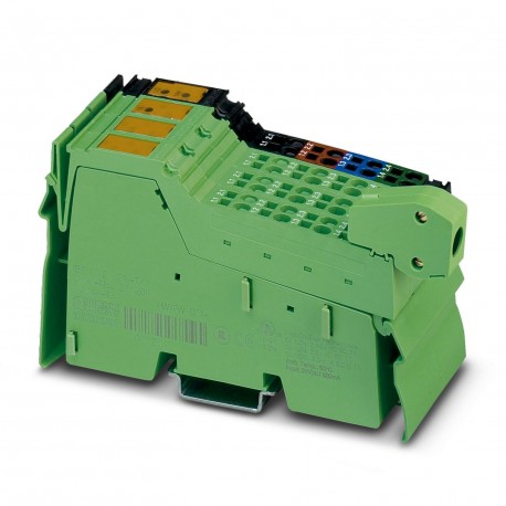
IB IL 24 LSKIP-PAC 2897457 PHOENIX CONTACT Inline function terminal
$0.00USD
4699 in stock
Key Specifications
:Protection against polarity reversal (segment supply/main supply); Parallel diodes for protection against polarity reversal; in the event of an error the high current flowing through the diodes causes the fuse connected upstream to blow.
Type:modular
Depth:71.5 mm
Width:48.8 mm
Supplier Information
Products: 0
Usually ships within 2-3 business days
Quality Guaranteed
Fast Shipping
Technical Support
Technical Specifications
| Parameter | Value |
|---|---|
| Protection against polarity reversal (segment supply/main supply); Parallel diodes for protection against polarity reversal; in the event of an error the high current flowing through the diodes causes the fuse connected upstream to blow. | |
| Type | modular |
| Depth | 71.5 mm |
| Width | 48.8 mm |
| Height | 135 mm |
| Current draw | max. 1.25 A (at nominal voltage; consisting of: 0.75 A DC for the communications power and 0.5 A DC for the analog voltage supply) |
| Product type | I/O component |
| ID code (hex) | none |
| Mounting type | DIN rail mounting |
| Product family | Inline |
| Supply voltage | 24 V DC (via Inline connector) |
| Connection name | Inline connector |
| Register length | 0 bit |
| Article revision | 06 |
| Protection class | III (IEC 61140, EN 61140, VDE 0140-1) |
| Stripping length | 8 mm |
| Connection method | Inline shield connector |
| Scope of delivery | including Inline connectors and marking fields |
| Input address area | 0 Byte |
| Protective circuit | Surge protection (segment supply, main supply, 24 V supply); Input protective diodes (can be destroyed by permanent overload)Pulse loads up to 1500 W are short circuited by the input protective diode. |
| Special properties | for extending the Inline local bus |
| Transmission speed | 500 kbps / 2 Mbps (Can be used in Inline stations with these transmission speeds) |
| Dimensional drawing | |
| Note on application | Only for industrial use |
| Output address area | 0 Byte |
| Degree of protection | IP20 |
| Number of interfaces | 1 (incoming local bus) |
| Supply voltage range | 19.2 V DC ... 30 V DC (including all tolerances, including ripple) |
| Transmission physics | Copper |
| Required parameter data | 0 Byte |
| Air pressure (operation) | 70 kPa ... 106 kPa (up to 3000 m above sea level) |
| Conductor cross section AWG | 28 ... 16 |
| Required configuration data | 0 Byte |
| Conductor cross section rigid | 0.08 mm² ... 1.5 mm² |
| Note on the connection method | Standard INTERBUS cable |
| Conductor cross section, rigid | 0.08 mm² ... 1.5 mm² |
| Ambient temperature (operation) | -25 °C ... 55 °C |
| Air pressure (storage/transport) | 70 kPa ... 106 kPa (up to 3000 m above sea level) |
| Conductor cross section flexible | 0.08 mm² ... 1.5 mm² |
| Permissible humidity (operation) | 10 % ... 95 % (non-condensing) |
| Conductor cross section, flexible | 0.08 mm² ... 1.5 mm² |
| Ambient temperature (storage/transport) | -25 °C ... 85 °C |
| Number of devices with parameter channel | 63 |
| Permissible humidity (storage/transport) | 10 % ... 95 % (non-condensing) |
| Maximum power dissipation for nominal condition | 1.45 W |
| Number of local bus devices that can be connected | max. 63 (without additional power terminal block, observe allowable total current consumption) |
| Test voltage: 5 V supply incoming local bus / 24 V main supply, 24 V segment supply | 500 V AC, 50 Hz, 1 min. |
| Test voltage: 24 V main supply, 24 V segment supply, 24 V power supply for generating voltages ULand UANA/ functional ground | 500 V AC, 50 Hz, 1 min. |
| Test voltage: 7.5 V communications power, 24 V analog power supply, 24 V power supply for generating voltages ULand UANA/ functional ground | 500 V AC, 50 Hz, 1 min. |
| Test voltage: 5 V supply incoming local bus / 7.5 V communications power, 24 V analog power supply, 24 V power supply for generating voltages ULand UANA | 500 V AC, 50 Hz, 1 min. |
| Test voltage: 7.5 V communications power, 24 V analog power supply, 24 V power supply for generating voltages ULand UANA/ 24 V main supply, 24 V segment supply | 500 V AC, 50 Hz, 1 min. |
Product Description
Inline, Coupler terminal block, for expansion of the local bus Inline, transmission rate on the local bus: 500 kBit/s / 2 MBit/s, protection index: IP20, including inline connectors and marking fields
Key Features
- Industrial grade quality
- RoHS compliant
- CE certified
- 1-year warranty
Product Documents
Datasheet
Technical specifications and performance data
User Manual
Installation and operation guide


