In Stock Hot Product
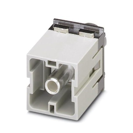
HC-M-HS 200/70-MOD-ST-PE
HC-M-HS 200/70-MOD-ST-PE 1636907 PHOENIX CONTACT Contact insert module
$0.00USD
4468 in stock
Key Specifications
GTIN:4046356095211
Note:Made to Order (non-returnable)
Orderkey:1636907
Catalog page:Page 551 (C-4-2015)
Supplier Information
Products: 0
Usually ships within 2-3 business days
Quality Guaranteed
Fast Shipping
Technical Support
Technical Specifications
| Parameter | Value |
|---|---|
| GTIN | 4046356095211 |
| Note | Made to Order (non-returnable) |
| Orderkey | 1636907 |
| Catalog page | Page 551 (C-4-2015) |
| Packing unit | 1 pc |
| Country of origin | DE (Germany) |
| Custom tariff number | 85366990 |
| (Ambient conditions) | 16 mm (70 mm²) |
| Contact material (General) | Copper alloy |
| Rated current (Dimensions) | 200 A |
| Width (Key Commercial Data) | 34.2 mm |
| Height (Key Commercial Data) | 54.5 mm |
| Length (Key Commercial Data) | 29.4 mm |
| Connection profile (Dimensions) | PE |
| Contact carrier material (General) | PC |
| Contact surface material (General) | Ag |
| Series (Mechanical characteristics) | HC-M-HS |
| Weight per Piece (excluding packing) | 97.600 g |
| Hexagonal socket (Ambient conditions) | WAF 5 |
| Tightening torque (Ambient conditions) | 9 Nm (40 - 50 mm²) |
| Connection (Mechanical characteristics) | Note on axial connection technology:Only for stranded wires. The specified conductor cross sections refer to the geometric cross section of the cable used.Use of cables with a geometric cross section that differs greatly from the nominal cross section of the cable should be checked before use.The wiring space for axial screw technology is designed for fine strand cables according to VDE 0295 Class 5. Deviating cable structures (e.g., Class 6 cables) should be checked before use.Assembly instructionsBefore assembly, ensure that the tapered screw is turned back all the way (chamber is open). The cables must not be twisted. The wires should be inserted as far as they will go into the contact chamber (until the insulation touches the contact). Hold the wires in position and use the socket wrench to tighten. The used wire end should be cut off before connecting again. The connection screw may only be retightened once to prevent the litz wires from breaking. To prevent damage to the contact, the wire/cable should be mechanically intercepted at an appropriate distance from the connection point (e.g., by using a plate cutout). DIN VDE 0100-520:2003-06 contains information on how to do this correctly. The module cannot be used simultaneously with HC-B..-TMB-SD-IP65 and HC-B..-TMS-SD-IP65 protective covers.PE mounting plateThe PE plate must be pressed hard against the swing frame using the 4 screws. First loosen the 4 screws of the PE plate and then tighten them again once the module is fixed in the swing frame. |
| Minimum housing height (Ambient conditions) | 72 mm |
| Conductor cross section (Ambient conditions) | 40 mm² ... 70 mm² (The cross section specification refers to the geometric cross section of the cable used) |
| Connection method (Mechanical characteristics) | Axial screw connection |
| Connection in acc. with standard (Material data) | UL |
| Insertion/withdrawal cycles (Ambient conditions) | ≥ 500 |
| Connection cross section AWG (Ambient conditions) | 1 ... 00 |
| Assembly instructions (Mechanical characteristics) | - Use only flexible conductors,- Connection of wires with 5 mm an Allen wrench,- Housing height h ≥ 72 mm,- Connectors may only be operated without load/voltage. |
| Number of module slots (Mechanical characteristics) | 2 |
| Flammability rating according to UL 94 (Material data) | V0 |
| Wire diameter including insulation (Ambient conditions) | 12 mm (40 mm²) |
| Ambient temperature (operation) (Electrical characteristics) | -40 °C ... 125 °C |
| Stripping length of the individual wire (Ambient conditions) | 16 mm |
| Flammability rating according to UL 94 (Mechanical characteristics) | V0 |
Product Description
More details
Key Features
- Industrial grade quality
- RoHS compliant
- CE certified
- 1-year warranty
Product Documents
Datasheet
Technical specifications and performance data
User Manual
Installation and operation guide


