In Stock Hot Product
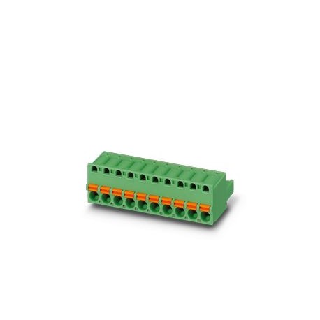
FKC 2,5/ 2-ST-5,08 BKBDWH-1QSO
FKC 2,5/ 2-ST-5,08 BKBDWH-1QSO 1530533 PHOENIX CONTACT PCB connector, nominal cross-section: 2.5 mm², colour..
$0.00USD
4205 in stock
Key Specifications
:Cross-section: 0.75 mm²; Length: 8 mm 10 mm
Link:Push-in spring connection
Step:5.08 mm
note:Complies with WEEE/RoHS, no thread-like materials according to IEC 60068-2-82/JEDEC JESD 201
Supplier Information
Products: 0
Usually ships within 2-3 business days
Quality Guaranteed
Fast Shipping
Technical Support
Technical Specifications
| Parameter | Value |
|---|---|
| Cross-section: 0.75 mm²; Length: 8 mm 10 mm | |
| Link | Push-in spring connection |
| Step | 5.08 mm |
| note | Complies with WEEE/RoHS, no thread-like materials according to IEC 60068-2-82/JEDEC JESD 201 |
| Result | Test passed |
| Amplitude | 0.35 mm (10 Hz ... 60.1 Hz) |
| Frequency | 10 - 150 - 10 Hz |
| Packaging | Packed in carton |
| Width [w] | 10.78 mm |
| Height [h] | 15 mm |
| Length [l] | 25.23 mm |
| Sweep Speed | 1 octave/min |
| Color (Case) | Black (9005) |
| No. of poles | 2 |
| Product Line | COMBICON Connectors M |
| Product Type | Printed circuit board connector |
| Clamping Type | absent |
| Fixing flange | absent |
| Number of rows | 1 |
| Product Family | FKC 2.5/.. -ST |
| Surface Finish | Hot-dip galvanizing |
| Connector system | COMBICON MSTB 2.5 |
| Contact Material | Cu Alloy |
| Fixed AC voltage | 2.21 kV |
| Mass Resistivity | 1 mΩ |
| Number of cycles | 25 |
| Rated Current IN | 12 A |
| Rated voltage UN | 320 V |
| Manoeuvring cycles | 25 |
| Note for Operation | According to DIN EN 61984, COMBICON connectors are switchable powerless (COC) connectors. For intended use, they must not be plugged in or disconnected when they are still energized or under load. |
| Test Specification | DIN EN 60999-1 (VDE 0609-1):2000-12 |
| Degree of pollution | 3 |
| Dimensioned Drawing | |
| Insulation material | PA |
| Mass Resistivity R1 | 1 mΩ |
| Mass Resistivity R2 | 1.1 mΩ |
| Nominal cross-section | 2.5 mm² |
| Sizing voltage (II/2) | 630 V |
| Colour (Drive Element) | Orange (2003) |
| Number of poles tested | 12 |
| Sizing voltage (III/2) | 320 V |
| Sizing voltage (III/3) | 320 V |
| Test duration per axle | 2.5 h |
| Contact Connection Type | female |
| Stress due to corrosion | 0.2 dm3KNOW2on 300 dm3/40 °C/1 cycle |
| Insulation Material Group | The |
| Recommended crimping tool | 1212034 CRIMPFOX 6 |
| CTI according to IEC 60112 | 600 |
| Conductor cross-section AWG | 24 ... 12 |
| Rated Impulse Voltage (II/2) | 4 kV |
| Buffer Gauge a x b / diameter | 2.8 mm x 2.0 mm / 2.4 mm |
| Minimum creepage value (II/2) | 3.2 mm |
| Rated impulse voltage (III/2) | 4 kV |
| Rated impulse voltage (III/3) | 4 kV |
| Rigid conductor cross-section | 0.2 mm² ... 2.5 mm² |
| Sizing Impulse Voltage (II/2) | 4 kV |
| Ambient temperature (mounting) | -5 °C ... 100 °C |
| Minimum creepage value (III/2) | 3 mm |
| Minimum creepage value (III/3) | 4 mm |
| Rated Isolation Voltage (II/2) | 630 V |
| Sizing Impulse Voltage (III/2) | 4 kV |
| Sizing impulse voltage (III/3) | 4 kV |
| Tensile force per pole approx. | 6 N |
| Ambient temperature (operating) | -40 °C ... 100 °C (depending on derating curve) |
| Rated Isolation Voltage (III/2) | 320 V |
| Flexible conductor cross-section | 0.2 mm² ... 2.5 mm² |
| Insertion force per pole approx. | 8 N |
| Rated insulation voltage (III/3) | 320 V |
| Stress due to the effect of heat | 100 °C/168 h |
| Conductor/board connection direction | 0 ° |
| Length of the section to be stripped | 10 mm |
| Ambient temperature (storage/transport) | -40 °C ... 70 °C |
| Combustibility class according to UL 94 | V0 |
| Vertical impulse tension above sea level | 4.8 kV |
| Relative humidity (transport and storage) | 30 % ... 70 % |
| Metal surface contact zone (surface layer) | Tin (4 - 8 μm Sn) |
| Insulation Resistance Between Contiguous Poles | > 5 MΩ |
| Metal Surface, Connection Point (Surface Layer) | Tin (4 - 8 μm Sn) |
| Minimum creepage value - inhomogeneous range (II/2) | 3 mm |
| Minimum creepage value - inhomogeneous range (III/2) | 3 mm |
| Minimum clearance value - inhomogeneous range (III/3) | 3 mm |
| Resistance to surface currents (DIN EN 60112 (VDE 0303-11)) | CTI 600 |
| Brinell hardness test temperature according to EN 60695-10-2 | 125 °C |
| GWIT filament ignition temperature according to EN 60695-2-13 | 775 |
| Flammability index of GWFI filament according to EN 60695-2-12 | 850 |
| cable lug with insulating collar, in accordance with DIN 46228-4 | Cross-section: 0.5 mm²; Length: 8 mm 10 mm |
| cable lug without insulating collar, in accordance with DIN 46228-1 | Cross-section: 0.5 mm²; Length: 8 mm 10 mm |
| Flexible conductor cross-section with mounted lug and plastic collar | 0.25 mm² ... 2.5 mm² |
| Direction of connection of the conductor to the direction of insertion | 0 ° |
| Flexible conductor cross-section with cable lug without plastic collar | 0.25 mm² ... 2.5 mm² |
| Conductor cross-section/conductor type/tensile force nominal value/actual value | 0.2 mm² / rigid / > 10 N |
| 2 conductors of identical cross-section flexible with TWIN ferrule with plastic collar | 0.5 mm² ... 1.5 mm² |
Product Description
PCB connector, nominal cross-section: 2.5 mm2, colour: black, rated current: 12 A, dimensioning voltage (III/2): 320 V, contact surface: tin, contact connection type: Female, number of rows: 1, number
Key Features
- Industrial grade quality
- RoHS compliant
- CE certified
- 1-year warranty
Product Documents
Datasheet
Technical specifications and performance data
User Manual
Installation and operation guide


