In Stock Hot Product
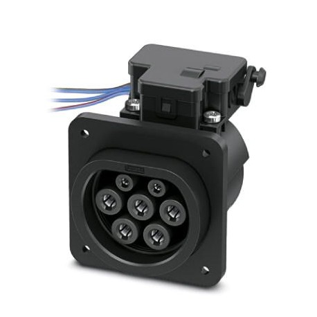
EV-T2M3SE12-0,18M-WBX-SET
EV-T2M3SE12-0,18M-WBX-SET 1068390 PHOENIX CONTACT Game made up of refuelling infrastructure, framework and p..
$0.00USD
4642 in stock
Key Specifications
EAN:Four trillion fifty five billion six hundred twenty six million seven hundred forty thousand nine hundred four
Key order:One million sixty eight thousand three hundred ninety
(Drawings):
Key selling:XWBADC -
Supplier Information
Products: 0
Usually ships within 2-3 business days
Quality Guaranteed
Fast Shipping
Technical Support
Technical Specifications
| Parameter | Value |
|---|---|
| EAN | Four trillion fifty five billion six hundred twenty six million seven hundred forty thousand nine hundred four |
| Key order | One million sixty eight thousand three hundred ninety |
| (Drawings) | |
| Key selling | XWBADC - |
| Life (Lock) | > 10000 cycles of load |
| Packing unit | 100 pcs |
| (Dimensions) | 185 mm ±10 mm (End of cable compacted 8 mm) |
| (Actuator lock) | You will find information about hazardous substances in the manufacturer's declaration in the "Downloads"tab |
| ETIM 6.0 (eCl@ss) | EC002898 |
| ETIM 7.0 (eCl@ss) | EC002898 |
| Material (Design) | Plastic |
| Cable length (Lock) | 0.5 m |
| Execution (Drawings) | Connection by screw protection cap in the rear |
| eCl@ss 9.0 (Ratings) | Twenty seven million one hundred forty four thousand seven hundred six |
| (Individual drivers) | IP54 (with protective cap; see accessories) |
| Line design (Mounting) | Standard |
| Lock system (Material) | Lock in a state connected with an actuator interlock |
| Minimum order quantity | 100 pcs |
| Observation (Drawings) | Game with a frame and protective cover |
| Product type (Drawings) | Game made up of refuelling infrastructure, framework and protective cap for charging with alternating current (AC) electric vehicles, compatible with charging connectors for infrastructure |
| Tension lock (Material) | 12 V |
| Charging mode (Drawings) | Mode 3, case B |
| Color housing (Mounting) | black |
| Standard load (Drawings) | Type 2 |
| China RoHS (Actuator lock) | Space of time for the intended use (FEUP): 10 years; |
| REACh SVHC (Actuator lock) | Lead 7439-92-1 |
| Detection of lock (Material) | existing |
| (Mechanical characteristics) | max. 10 mm (wall Mount, front, to use the actuator to lock) |
| Individual driver N (Dimensions) | BU |
| Depth (Definition of the product) | 76.2 mm |
| Individual driver CP (Dimensions) | WH |
| Individual driver CS (Dimensions) | RD |
| Individual driver L1 (Dimensions) | |
| Individual driver L2 (Dimensions) | BK |
| Individual driver L3 (Dimensions) | GY |
| Individual driver PE (Dimensions) | GN/YE |
| Locked current max. engine (Lock) | 1 To |
| Motor current typical lock (Lock) | 0.2 To |
| Power supply typical motor (Lock) | 12 V |
| Room temperature (service) (Lock) | -30 °C ... 50 °C |
| Unit weight (excluding packaging) | 564,000 g |
| Width (Definition of the product) | 75 mm |
| Altitude max. (Individual drivers) | 5000 m (above sea level) |
| Height (Definition of the product) | 96 mm |
| Standards/specifications (Drawings) | IEC 62196-2 |
| Time of adaptation recommended (Lock) | 600 ms |
| Cycles of plug (Electrical properties) | > 10000 |
| Dwell time max. with power lock (Lock) | 1000 ms |
| Insertion force (Electrical properties) | < 100 N |
| Cable length (Definition of the product) | 0.18 m |
| Index of protection (Individual drivers) | IP44 (inserted) |
| Type of cable (Definition of the product) | Individual drivers |
| DiagramStates lock actuator lock (Drawings) | |
| Force of separation (Electrical properties) | < 100 N |
| Number of phases (Environmental conditions) | Three |
| Mechanical unlocking of emergency (Material) | existing |
| Note about the type of connection (Drawings) | Connection set, not separable |
| Structure of cable (Definition of the product) | 5x 6,0 mm2 + 2x 0.5 mm2 |
| Dimensions of drill (Definition of the product) | 60 mm x 60 mm |
| Outline dimensionsOutline dimensions (Drawings) | |
| Pause time after an input path or output (Lock) | 3 s |
| Room temperature (service) (Individual drivers) | -30 °C ... 50 °C |
| Type of load current (Environmental conditions) | AC three-phase |
| Power of maximum load (Environmental conditions) | 22 kW |
| Surface of the material of the contacts (Design) | Ag |
| Wall thickness max. (Mechanical characteristics) | max. 50 mm (Mounting on rear wall, maximum specification standards for charging connectors for infrastructures) |
| Number of power contacts (Environmental conditions) | 5 (L1, L2, L3, N, PE) |
| Maximum voltage for the detection of the lock (Lock) | 30 V |
| Number of signal contacts (Environmental conditions) | 2 (CP, PP) |
| Possible range of supply voltage in the motor (Lock) | 9 V ... 16 V |
| Power contacts rated current (Environmental conditions) | 32 To |
| Power contacts rated voltage (Environmental conditions) | 480 V AC |
| Contacts notice rated current (Environmental conditions) | 2 To |
| Contacts notice rated voltage (Environmental conditions) | 30 V AC |
| Diameter of the fixing hole (Mechanical characteristics) | 7,00 mm (ø) |
| Possible mounting positions (Mechanical characteristics) | Mounting on back wall |
| Individual threads of the actuator interlock (Dimensions) | BU/RD |
| Type of transmission of signals (Environmental conditions) | Modulation of duration of impulses |
| Mounting position actuator lock (Mechanical characteristics) | In the upper center |
| Note about the type of connection (Environmental conditions) | Connection set, not separable |
| Ambient temperature (storage / transport) (Individual drivers) | -40 °C ... 80 °C |
| Limitations of the mounting position (Mechanical characteristics) | Just tilt the front from 0 to 90 degrees as possible, see figure |
| Connection by screw of a protection cap (Mechanical characteristics) | only possible on the back side |
| Schematic drawingDetection of charging connector for infrastructure (Drawings) | |
| Drawing of connectionArrangement of pins of the cargo box infrastructure (Drawings) | |
| Schematic drawingThickness of wall mounting rear wall (max. 50 mm, with protective cap Phoenix Contact max. 22 mm) (Drawings) | |
| Schematic drawingFront mounting connection by screw protection cap in the rearThe front-mounting is only possible if the actuator lock is removed. For this reason we recommend the use of an electrical charging infrastructure without actuator latch previously mounted (EV-T2M3SE-...E0..., e.g. 1621729).The connection screw of a protection cap of the range of accessories (EV-T2SC) is only possible on the back side. The wall thickness should not exceed 10 mm The frame of the shutter is inserted in front should align with the flat side in the wall of the housing and completely surround the electrical charging infrastructure. (Drawings) |
Product Description
CHARX connect, Set, Combination of infrastructure charging socket, frame and protective cap, screw connection of protective cover at the rear, For charging electric vehicles (EV) with alternating curr
Key Features
- Industrial grade quality
- RoHS compliant
- CE certified
- 1-year warranty
Technical Details
Drawing of connectionArrangement of pins of the cargo box infrastructure
Product Documents
Datasheet
Technical specifications and performance data
User Manual
Installation and operation guide


