In Stock Hot Product
DFK-IPC 16/ 7-GF-SH-10,16
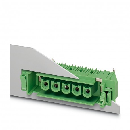
DFK-IPC 16/ 7-GF-SH-10,16 1703027 PHOENIX CONTACT Feed-through header
$23.43USD
461 in stock
Key Specifications
Note:WEEE/RoHS-compliant, free of whiskers according to IEC 60068-2-82/JEDEC JESD 201
Type:Feed-through header
Pitch:10.16 mm
Result:Test passed
Supplier Information
Products: 0
Usually ships within 2-3 business days
Quality Guaranteed
Fast Shipping
Technical Support
Technical Specifications
| Parameter | Value |
|---|---|
| Note | WEEE/RoHS-compliant, free of whiskers according to IEC 60068-2-82/JEDEC JESD 201 |
| Type | Feed-through header |
| Pitch | 10.16 mm |
| Result | Test passed |
| Amplitude | 0.35 mm (10 Hz ... 60.1 Hz) |
| Frequency | 10 - 150 - 10 Hz |
| Width [w] | 112.2 mm |
| Height [h] | 22 mm |
| Length [l] | 34.55 mm |
| Pin layout | Linear pinning |
| Pin spacing | 10.16 mm |
| Sweep speed | 1 octave/min |
| Acceleration | 5g (60.1 Hz ... 150 Hz) |
| Product line | COMBICON Connectors XL |
| Product type | Feed-through header |
| Hole diameter | 1.7 mm |
| Mounting type | Wave soldering |
| No. of cycles | 50 |
| Specification | IEC 60512-1:2001-01 |
| Number of rows | 1 |
| Pin dimensions | 0.8 x 1.2 mm |
| Product family | DFK-IPC 16/..-GF-SH |
| Thermal stress | 100 °C/168 h |
| Color (Housing) | green (6021) |
| Mounting flange | Threaded flange |
| Test directions | X-, Y- and Z-axis |
| Article revision | 02 |
| Contact material | Cu alloy |
| Corrosive stress | KFW 0.2 S/1 cycle |
| Installed height | 19.9 mm |
| Type of packaging | packed in cardboard |
| Contact resistance | 0.3 mΩ |
| Nominal current IN | 76 A |
| Nominal voltage UN | 1000 V |
| Notes on operation | In accordance with IEC 61984, COMBICON connectors have no switching power (COC). During designated use, they must not be plugged in or disconnected when carrying voltage or under load. |
| Dimensional drawing | |
| Insulating material | PA |
| Number of positions | 7 |
| Number of potentials | 7 |
| Rated voltage (II/2) | 1000 V |
| Contact resistance R1 | 0.3 mΩ |
| Contact resistance R2 | 0.4 mΩ |
| Number of connections | 7 |
| Rated voltage (III/2) | 1000 V |
| Rated voltage (III/3) | 1000 V |
| Solder pin length [P] | 4.1 mm |
| Test duration per axis | 2.5 h |
| Surface characteristics | completely silver-plated |
| Electrical characteristic | shielded |
| Insulating material group | I |
| Solder pins per potential | 3 |
| CTI according to IEC 60112 | 600 |
| Rated surge voltage (II/2) | 6 kV |
| Tested number of positions | 9 |
| Insertion/withdrawal cycles | 50 |
| Rated surge voltage (III/2) | 8 kV |
| Rated surge voltage (III/3) | 8 kV |
| Ambient temperature (assembly) | -5 °C ... 100 °C |
| Ambient temperature (operation) | -40 °C ... 100 °C (dependent on the derating curve) |
| Rated insulation voltage (II/2) | 1000 V |
| Rated insulation voltage (III/2) | 1000 V |
| Rated insulation voltage (III/3) | 1000 V |
| minimum creepage distance (II/2) | 5.5 mm |
| Power-frequency withstand voltage | 4.26 kV |
| minimum creepage distance (III/2) | 8 mm |
| minimum creepage distance (III/3) | 12.5 mm |
| Withdraw strength per pos. approx. | 9 N |
| Insertion strength per pos. approx. | 10 N |
| Relative humidity (storage/transport) | 30 % ... 70 % |
| Flammability rating according to UL 94 | V0 |
| Impulse withstand voltage at sea level | 9.8 kV |
| Metal surface contact area (top layer) | Silver (4 - 8 µm Ag) |
| Ambient temperature (storage/transport) | -40 °C ... 70 °C |
| Comparative tracking index (IEC 60112) | CTI 600 |
| Metal surface soldering area (top layer) | Silver (4 - 8 µm Ag) |
| Contact holder in insertRequirements >20 N | Test passed |
| Insulation resistance, neighboring positions | 1012Ω |
| minimum clearance value - non-homogenous field (II/2) | 5.5 mm |
| minimum clearance value - non-homogenous field (III/2) | 8 mm |
| minimum clearance value - non-homogenous field (III/3) | 8 mm |
| Glow wire flammability index GWFI according to EN 60695-2-12 | 850 |
| Glow wire ignition temperature GWIT according to EN 60695-2-13 | 775 |
| Temperature for the ball pressure test according to EN 60695-10-2 | 125 °C |
Product Description
Wall pass-through housing, nominal section: 16 mm², color: green, nominal current: 76 A, nominal voltage (III/2): 1000 V, contact surface: silver, contact type: Female, number of potentials: 7, number
Key Features
- Industrial grade quality
- RoHS compliant
- CE certified
- 1-year warranty
Product Documents
Datasheet
Technical specifications and performance data
User Manual
Installation and operation guide


