In Stock Hot Product
DA1-32024FB-A20N
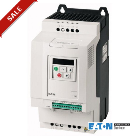
DA1-32024FB-A20N 169173 EATON ELECTRIC PowerXL Drive Series DA1
$0.00USD
4138 in stock
Key Specifications
:
Note:
Size:
Power:
Supplier Information
Products: 0
Usually ships within 2-3 business days
Quality Guaranteed
Fast Shipping
Technical Support
Technical Specifications
| Parameter | Value |
|---|---|
| Note | |
| Size | |
| Power | |
| Range | |
| depth | |
| width | |
| height | |
| Storage | ϑ |
| voltage | |
| Function | |
| Equipment | |
| Operation | |
| Power part | |
| Performance | η |
| UL File No. | |
| CSA File No. | |
| Start engine | |
| Suitable for | |
| 10.10 Warm-up | |
| Analog inputs | |
| Relay outputs | |
| 150 % Overload | P |
| Analog outputs | |
| Apparent power | |
| Certifications | |
| Clock frequency | fPWM |
| Frequency power | |
| Frequency range | fLN |
| Safety function | |
| Type identifier | |
| 10.2.5 Elevation | |
| Braking function | |
| Output frequency | fTwo |
| Power dissipated | |
| Voltage setpoint | Us |
| 10.2.6 shock Test | |
| Environment (EMC) | |
| Mounting Position | |
| Network frequency | fLN |
| Product Standards | |
| Rated current job | |
| type of converter | |
| Climate resilience | ρw |
| Output voltage (Ue | UTwo |
| 10.2.7 Inscriptions | |
| Ambient temperature | |
| Max. Voltage Rating | |
| 10 % duty cycle (FM) | |
| 20 % duty cycle (FM) | |
| Degree of Protection | |
| Degree of protection | |
| output voltage: max. | |
| with control element | |
| Manufacturing quality | |
| output frequency max. | |
| protection class (IP) | |
| with connection to PC | |
| 10.6 Mounting hardware | |
| Entries all-or-nothing | |
| Outputs all-or-nothing | |
| number of input phases | |
| with optical interface | |
| (IEC Type B, gG), 150 % | |
| 10.2.4 Resistance to UV | |
| Braking torque Standard | |
| Mains voltage (50/60Hz) | ULN |
| UL Category Control No. | |
| frequency of the sector | |
| number of phases output | |
| Altitude of installation | |
| chopper integrated brake | |
| control voltage external | Uc |
| for an overload of 150 % | Ie |
| Braking torque Braking dc | |
| Compliance with standards | |
| Connection to the network | |
| UL listed (Class CC or J) | |
| 10.13 mechanical Operation | |
| 10.9.3 there Voltage shock | |
| Connection to SmartWire-DT | |
| Engine power corresponding | |
| Service (150 % surcharge). | ϑ |
| output current nominal I2N | |
| supported protocol for ASI | |
| supported protocol for CAN | |
| supported protocol for KNX | |
| supported protocol for LON | |
| North America Certification | |
| Rated voltage of employment | Ue |
| 10.9 Properties of isolation | |
| Certificate for IEC/EN 61439 | |
| maximum length of motor cable | I |
| supported protocol for MODBUS | |
| supported protocol for SERCOS | |
| supported protocol for TCP/IP | |
| 10.2.2 Resistance to corrosion | |
| External braking resistor min. | Rmin |
| Input current (overload 150 %) | ILN |
| Interface/field bus (built-in) | |
| supported protocol for SUCONET | |
| 10.9.4 Test envelope insulation | |
| 150 % overload (CT/IHat 50 °C) | |
| supported protocol for INTERBUS | |
| supported protocol for PROFIBUS | |
| supported protocol for DeviceNet | |
| supported protocol for PROFIsafe | |
| Level of interference suppression | |
| Overload current (overload 150 %) | IThe |
| number of hardware interfaces USB | |
| 10.11 resistance to short-circuits | |
| Protection against direct contacts | |
| supported protocol for EtherNet/IP | |
| supported protocol for PROFINET IO | |
| supported protocol for SafetyBUS p | |
| 10.12 electromagnetic Compatibility | |
| Maximum permissible length of cable | I |
| supported protocol for Data-Highway | |
| supported protocol for PROFINET CBA | |
| use permitted in an industrial zone | |
| 10.2 Strength of materials and parts | |
| Class interference suppression (EMC) | |
| Specially designed for North America | |
| operation possible in four quadrants | |
| Apparent power in rated service 230 V | S |
| Apparent power in rated service 240 V | S |
| Module coupling to field bus (option) | |
| a number of other hardware interfaces | |
| 10.5 Protection against electric shock | |
| Resolution of the frequency (setpoint) | Δf |
| number of hardware interfaces PROFINET | |
| number of hardware interfaces parallel | |
| supported protocol for INTERBUS-Safety | |
| supported protocol for DeviceNet Safety | |
| 10.2.3.1 heat Resistance of the envelope | |
| number of hardware interfaces serial TTY | |
| supported protocol for other bus systems | |
| 10.3 Degree of protection of the envelope | |
| supported protocol for Foundation Fieldbus | |
| Power dissipated under current assigned job | PV |
| number of hardware interfaces RS-232 serial | |
| number of hardware interfaces RS-485 serial | |
| number of hardware interfaces serial RS-422 | |
| 10.4 isolation Distances and lines of flight | |
| Braking torque with external braking resistor | |
| Peak current at start-up max. (High Overload) | IH |
| A note about the peak current at start-up max. | |
| Activation threshold for the braking transistor | UDC |
| 10.9.2 withstand Voltage at industrial frequency | |
| permitted use in residential and commercial area | |
| 10.7 electrical Circuits and connections internal | |
| number of hardware interfaces Industrial Ethernet | |
| output power max. linear load voltage output rated | |
| supported protocol for AS-Interface Safety at Work | |
| Technical specifications for verification of design | |
| tolerance relative frequency of the symmetrical network | |
| Leakage current maximum at the ground (PE) without motor | IPE |
| Rated current job for indication of the power dissipated | In |
| relative tolerance of voltage of the symmetrical network | |
| 10.2.3.2 Resistance of insulating Materials to Heat normal | |
| 10.8 Connections for the conductors passed from the outside | |
| Power dissipated in the material, a function of the current | Pvid |
| output power max. support quadratic in output voltage rated | |
| 10.2.3.3 Resistance insulating Materials for outstanding Warmth |
Product Description
More details
Key Features
- Industrial grade quality
- RoHS compliant
- CE certified
- 1-year warranty
Product Documents
Datasheet
Technical specifications and performance data
User Manual
Installation and operation guide


