In Stock Hot Product
D32H 2,2/ 2-H-5,08-Y
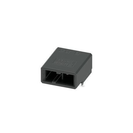
D32H 2,2/ 2-H-5,08-Y 1376496 PHOENIX CONTACT Printed circuit board base housing, color: black, rated current..
$1.10USD
9139 in stock
Key Specifications
:3 mm
Step:5.08 mm
Result:Approved Test
Amplitude:0.35 mm (10 Hz ... 60.1 Hz)
Supplier Information
Products: 0
Usually ships within 2-3 business days
Quality Guaranteed
Fast Shipping
Technical Support
Technical Specifications
| Parameter | Value |
|---|---|
| 3 mm | |
| Step | 5.08 mm |
| Result | Approved Test |
| Amplitude | 0.35 mm (10 Hz ... 60.1 Hz) |
| Width [w] | 19.08 mm |
| frequency | 10 - 150 - 10 Hz |
| Height [h] | 13.15 mm |
| Length [l] | 22.1 mm |
| Pin Design | Linear Pin Arrangement |
| Shock Type | Semi-sinusoid |
| Observation | WEEE/RoHS compliant, filament-free according to IEC 60068-2-82/JEDEC JESD 201 |
| Plug Cycles | 25 |
| Sweep speed | 1 octave/min |
| Acceleration | 30g |
| Product Line | CONNEXIS Connectors M |
| Product Type | Printed circuit board base housing |
| Hole diameter | 1.1 mm |
| Number of rows | 1 |
| Overall Height | 9.35 mm |
| Product Family | D32H 2,2/.. -H |
| Thermal stress | 105 °C/168 h |
| Color (Housing) | Black (9005) |
| Note on contact | These are connectors without switching capability (COC) according to DIN EN 61984. In the event of use as prescribed, they must not be plugged in or unplugged under voltage or load. |
| Number of poles | 2 |
| Test Directions | X, Y, and Z axes (pos. and neg.) |
| Contact material | Cu Alloy |
| Dimension Scheme | |
| Number of cycles | 25 |
| Type of mounting | Wave soldering |
| Corrosion fatigue | 0.2 dm3UNDER2in 300 dm3/40 °C/1 cycle |
| Type of packaging | Boxed Packaging |
| Contact resistance | 0.9 mΩ |
| Nominal Current IN | 8 A |
| Nominal voltage UN | 320 V |
| Test Specification | DIN EN 60512-1-1:2003-01 |
| Bearable AC voltage | 2.21 kV |
| Degree of pollution | 3 |
| Insulating material | PBT |
| Weld Pin Length [P] | 3.8 mm |
| Contact Resistance R1 | 0.9 mΩ |
| Contact Resistance R2 | 1 mΩ |
| Duration of the crash | 11 ms |
| Plug-in force approx. | 3 N |
| Nominal voltage (II/2) | 600 V |
| Number of poles tested | 10 |
| Sizing voltage (III/3) | 250 V |
| Test duration per axis | 2.5 h |
| Surface Characteristics | Galvanically tinned |
| Insulating material group | Ii |
| CTI according to IEC 60112 | 400 ≤ CTI |
| Dimensioning voltage (III/2) | 320 V |
| Ambient Temperature (Service) | -55 °C ... 105 °C (depending on the rating curve) |
| Ambient Temperature (Mounting) | -5 °C ... 100 °C |
| Nominal transient voltage (II/2) | 4 kV |
| Sizing Insulation Voltage (II/2) | 600 V |
| Nominal transient voltage (III/2) | 4 kV |
| Nominal transient voltage (III/3) | 4 kV |
| Sizing Insulation Voltage (III/2) | 320 V |
| Sizing Insulation Voltage (III/3) | 250 V |
| Minimum creepage line value (II/2) | 4.5 mm |
| Bearable shock voltage at sea level | 4.8 kV |
| Metal surface weld area (top layer) | Tin (3 - 5 μm Sn) |
| Minimum creepage line value (III/2) | 3 mm |
| Minimum creepage line value (III/3) | 3.6 mm |
| Number of Solder Pins Per Potential | 1 |
| Contact Holder UsedRequirement >20 N | Approved Test |
| Insulation Resistance Adjacent Poles | > 5 MΩ |
| Dimensioning transient voltage (II/2) | 4 kV |
| Flammability class according to UL 94 | V0 |
| Power when unplugging by pole approx. | 4 N |
| Dimensioning Transient Voltage (III/2) | 4 kV |
| Dimensioning transient voltage (III/3) | 4 kV |
| Metal surface contact area (top layer) | Tin (3 - 5 μm Sn) |
| Ambient Temperature (Storage/Transport) | -40 °C ... 70 °C |
| Metal Surface Contact Area (Middle Layer) | Nickel (1.3 - 3 μm Ni) |
| Metal Surface Welding Area (Middle Layer) | Nickel (1.3 - 3 μm Ni) |
| Relative humidity of the air (storage/transport) | 30 % ... 70 % |
| Resistance to leakage currents (DIN EN 60112 (VDE 0303-11)) | CTI ≥400 to <600 |
| Minimum Value of Air Insulation Distance - Non-Homogeneous Field (II/2) | 3 mm |
| Minimum Value of Air Insulation Distance - Non-Homogeneous Field (III/2) | 3 mm |
| minimum value of air insulation distance - non-homogeneous field (III/3) | 3 mm |
Product Description
PCB base housing, color: black, rated current: 8 A, rated voltage (III/2): 320 V, surface contacts: tin, contact type: Male, number of rows: 1, number of poles: 2, item family: D32H 2,2/.. -H, pitch:
Key Features
- Industrial grade quality
- RoHS compliant
- CE certified
- 1-year warranty
Product Documents
Datasheet
Technical specifications and performance data
User Manual
Installation and operation guide


