In Stock Hot Product
CABLE-D-15SUB/F/OE/0,25/S/6,0M
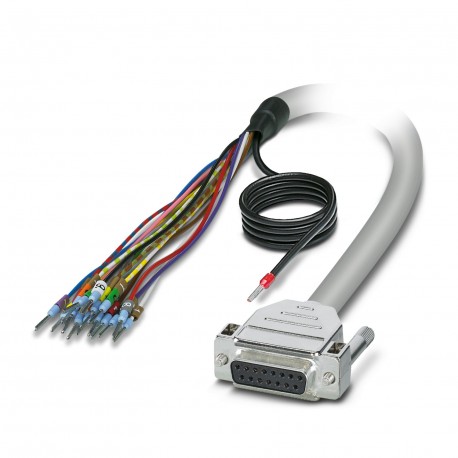
CABLE-D-15SUB/F/OE/0,25/S/6,0M 2926140 PHOENIX CONTACT Cable
$0.00USD
3830 in stock
Key Specifications
:-10 °C ... 70 °C (flexible installation)
red:D-SUB15 (8) = ()
Note:The wires are marked and fitted with ferrules. The braided shield is routed to a separate cable end.
blue:D-SUB15 (7) = ()
Supplier Information
Products: 0
Usually ships within 2-3 business days
Quality Guaranteed
Fast Shipping
Technical Support
Technical Specifications
| Parameter | Value |
|---|---|
| -10 °C ... 70 °C (flexible installation) | |
| red | D-SUB15 (8) = () |
| Note | The wires are marked and fitted with ferrules. The braided shield is routed to a separate cable end. |
| blue | D-SUB15 (7) = () |
| gray | D-SUB15 (5) = () |
| pink | D-SUB15 (6) = () |
| Pitch | 2.74 mm |
| black | D-SUB15 (9) = () |
| brown | D-SUB15 (2) = () |
| green | D-SUB15 (3) = () |
| white | D-SUB15 (1) = () |
| violet | D-SUB15 (10) = () |
| yellow | D-SUB15 (4) = () |
| Altitude | ≤ 2000 m |
| Shielded | yes |
| red-blue | D-SUB15 (12) = () |
| gray-pink | D-SUB15 (11) = () |
| Cable type | 15X0.25 [PVC] |
| brown-green | D-SUB15 (14) = () |
| white-green | D-SUB15 (13) = () |
| Cable length | 6 m |
| Halogen-free | no |
| Product type | System cable |
| Screw thread | UNC 4-40 |
| UL AWM Style | 2464/1061 |
| white-yellow | D-SUB15 (15) = () |
| Conductor type | Assembled shielded round cable |
| AWG signal line | 24 |
| Article revision | 02 |
| Cable resistance | ≤ 80 Ω/km (at 20 °C) |
| Flame resistance | IEC 60332-1-2 (raw cable) |
| Connection method | Single wires |
| Resistance to oil | can withstand occasional splashes (raw cable) |
| Tightening torque | 0.2 Nm |
| Conductor material | Bare Cu litz wires |
| Current (Per path) | ≤ 2 A (Uncoiled, see derating) |
| Notes on operation | No additional touch protection is required when using a SELV/PELV voltage (≤30 V AC or 60 V DC). |
| Number of positions | 15 |
| Degree of protection | IP20 |
| Insulation resistance | ≥ 20 MΩ*km (at 20 °C) |
| Number of connections | 1 |
| External sheath, color | gray |
| Nominal operating mode | 100% operating factor |
| Operating voltage (AC) | ≤ 30 V AC |
| Operating voltage (DC) | ≤ 60 V DC |
| Outer sheath, material | Semi-rigid PVC |
| Conductor cross section | 15x 0.25 mm² |
| External cable diameter | 7.90 mm ±0.5 mm |
| Stripping length (Sheath) | 150 mm |
| Insertion/withdrawal cycles | > 200 |
| Wire diameter incl. insulation | 1.2 mm ±0.05 mm |
| Ambient temperature (operation) | -40 °C ... 70 °C (fixed installation) |
| Conductor structure signal line | 14x 0.15 mm |
| Dynamic load capacity (bending) | Max. bending cycles: 5000 (at a radius of ≥ 15x outside diameter) |
| Connection in acc. with standard | IEC 60807-2 |
| Ambient temperature (storage/transport) | -40 °C ... 80 °C |
| Smallest bending radius, fixed installation | 67 mm |
| Degree of protection (Installation location) | ≥ IP54 (Installation location) |
| Smallest bending radius, movable installation | 126 mm |
Product Description
Shielded ready-made round cable; Connection 1: Single conductors (15-poles) (The conductors are labeled and equipped with ferrules. The braided screen protrudes from the separate cable end.); Connecti
Key Features
- Industrial grade quality
- RoHS compliant
- CE certified
- 1-year warranty
Product Documents
Datasheet
Technical specifications and performance data
User Manual
Installation and operation guide


