In Stock Hot Product
BCH-381VF-4 GN
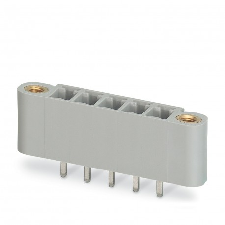
BCH-381VF- 4 GN 5444851 PHOENIX CONTACT Housing base,nominal Current: 8 A,rated Voltage (III/2): 160 V,N. º ..
$0.00USD
3985 in stock
Key Specifications
Step:3.81 mm
Result:Approved Test
Amplitude:0.35 mm (10 Hz ... 60.1 Hz)
Width [w]:25.63 mm
Supplier Information
Products: 0
Usually ships within 2-3 business days
Quality Guaranteed
Fast Shipping
Technical Support
Technical Specifications
| Parameter | Value |
|---|---|
| Step | 3.81 mm |
| Result | Approved Test |
| Amplitude | 0.35 mm (10 Hz ... 60.1 Hz) |
| Width [w] | 25.63 mm |
| frequency | 10 - 150 - 10 Hz |
| Height [h] | 12.6 mm |
| Length [l] | 7.4 mm |
| Pin Design | Linear Pin Arrangement |
| Observation | WEEE/RoHS compliant, filament-free according to IEC 60068-2-82/JEDEC JESD 201 |
| Plug Cycles | 25 |
| Sweep speed | 1 octave/min |
| Acceleration | 5g (60.1 Hz ... 150 Hz) |
| Construction | Standard |
| Product Line | COMBICON Connectors S |
| Product Type | Printed circuit board base housing |
| Hole diameter | 1.2 mm |
| Article Review | 02 |
| Number of rows | 1 |
| Overall Height | 9.2 mm |
| Product Family | BCH-VF |
| Thermal stress | 100 °C/168 h |
| Clamping flange | Overhead clamping (thread) |
| Color (Housing) | off-white green (6019) |
| Number of poles | 4 |
| Test Directions | X, Y, and Z axes |
| Contact material | Cu Alloy |
| Dimension Scheme | |
| Number of cycles | 25 |
| Type of mounting | Wave soldering |
| Corrosion fatigue | 0.2 dm3UNDER2in 300 dm3/40 °C/1 cycle |
| Temple Dimensions | 0.8 x 0.8 mm |
| Tightening torque | 0.3 Nm |
| Type of packaging | Boxed Packaging |
| Contact resistance | 4.3 mΩ |
| Nominal Current IN | 8 A |
| Nominal voltage UN | 160 V |
| Test Specification | DIN EN 60512-1-1:2003-01 |
| Bearable AC voltage | 1.39 kV |
| Insulating material | PA |
| Weld Pin Length [P] | 3.4 mm |
| Number of potentials | 4 |
| Contact Resistance R1 | 4.3 mΩ |
| Contact Resistance R2 | 4.3 mΩ |
| Number of connections | 4 |
| Plug-in force approx. | 5 N |
| Nominal voltage (II/2) | 320 V |
| Number of poles tested | 16 |
| Sizing voltage (III/3) | 160 V |
| Test duration per axis | 2.5 h |
| Surface Characteristics | Galvanically tinned |
| Insulating material group | I |
| CTI according to IEC 60112 | 600 |
| Dimensioning voltage (III/2) | 160 V |
| Ambient Temperature (Service) | -40 °C ... 100 °C (depending on the rating curve) |
| Ambient Temperature (Mounting) | -5 °C ... 100 °C |
| Nominal transient voltage (II/2) | 2.5 kV |
| Sizing Insulation Voltage (II/2) | 320 V |
| Nominal transient voltage (III/2) | 2.5 kV |
| Nominal transient voltage (III/3) | 2.5 kV |
| Sizing Insulation Voltage (III/2) | 160 V |
| Sizing Insulation Voltage (III/3) | 160 V |
| Minimum creepage line value (II/2) | 1.6 mm |
| Bearable shock voltage at sea level | 2.95 kV |
| Metal surface weld area (top layer) | Tin (4 - 8 μm Sn) |
| Minimum creepage line value (III/2) | 1.5 mm |
| Minimum creepage line value (III/3) | 2 mm |
| Number of Solder Pins Per Potential | 1 |
| Insulation Resistance Adjacent Poles | > 5 MΩ |
| Dimensioning transient voltage (II/2) | 2.5 kV |
| Flammability class according to UL 94 | V0 |
| Power when unplugging by pole approx. | 3 N |
| Dimensioning Transient Voltage (III/2) | 2.5 kV |
| Dimensioning transient voltage (III/3) | 2.5 kV |
| Metal surface contact area (top layer) | Tin (4 - 8 μm Sn) |
| Ambient Temperature (Storage/Transport) | -40 °C ... 70 °C |
| Metal Surface Contact Area (Middle Layer) | Nickel (1.5 - 4 μm Ni) |
| Metal Surface Welding Area (Middle Layer) | Nickel (1.5 - 4 μm Ni) |
| Relative humidity of the air (storage/transport) | 30 % ... 70 % |
| Ball hardness test temperature according to EN 60695-10-2 | 125 °C |
| Resistance to leakage currents (DIN EN 60112 (VDE 0303-11)) | CTI 600 |
| Minimum Value of Air Insulation Distance - Non-Homogeneous Field (II/2) | 1.5 mm |
| Minimum Value of Air Insulation Distance - Non-Homogeneous Field (III/2) | 1.5 mm |
| minimum value of air insulation distance - non-homogeneous field (III/3) | 1.5 mm |
| Flammability number of GWFI incandescent filaments according to EN 60695-2-12 | 850 |
| Ignition temperature of incandescent filaments GWIT according to EN 60695-2-13 | 775 |
Product Description
Printed circuit board base housing, nominal section: 1.5 mm², color: whitish green, nominal current: 8 A, nominal voltage (III/2): 160 V, contact surface: Tin, contact type: Male, number of potentials
Key Features
- Industrial grade quality
- RoHS compliant
- CE certified
- 1-year warranty
Product Documents
Datasheet
Technical specifications and performance data
User Manual
Installation and operation guide


