In Stock Hot Product
AXL F DOR4/2 AC/220DC 1F
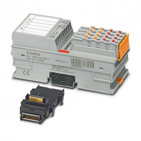
AXL F DOR4/2 AC/220DC 1F 2700608 PHOENIX CONTACT I/O module
$0.00USD
4692 in stock
Key Specifications
:For DC see load limit curve, e.g., the following values:
Type:block modular
Depth:54 mm
Width:53.6 mm
Supplier Information
Products: 0
Usually ships within 2-3 business days
Quality Guaranteed
Fast Shipping
Technical Support
Technical Specifications
| Parameter | Value |
|---|---|
| For DC see load limit curve, e.g., the following values: | |
| Type | block modular |
| Depth | 54 mm |
| Width | 53.6 mm |
| Height | 126.1 mm |
| Current draw | max. 280 mA (all relays pick up) |
| Product type | I/O component |
| Mounting type | DIN rail mounting |
| Product family | Axioline F |
| Supply voltage | 5 V DC (via bus base module) |
| Connection name | Axioline F connector |
| Article revision | 02 |
| Pollution degree | 2 |
| Stripping length | 8 mm |
| Connection method | Bus base module |
| Mounting position | any (observe temperature and current derating) |
| Number of outputs | 4 (floating) |
| Scope of delivery | including bus base module and Axioline F connectors |
| Switching current | max. 8 A AC (cos phi = 1) |
| Input address area | 0 Byte |
| Note on dimensions | The depth applies when a TH 35-7.5 DIN rail is used (in accordance with EN 60715). |
| Switching capacity | max. 2000 VA |
| Transmission speed | 100 Mbps |
| Dimensional drawing | |
| Note on application | Only for industrial use |
| Output address area | 1 Byte |
| Switching frequency | max. 6 (per minute) |
| Degree of protection | IP20 |
| Number of interfaces | 2 |
| Overvoltage category | III (EN 61010-2-201/UL 61010-2-201), up to 2000 m above sea levelII (EN 61010-2-201/UL 61010-2-201), up to 3000 m above sea level |
| Standard designation | Ambient conditions |
| Connection technology | 2-conductor |
| Contact switching type | N/O contact |
| Mechanical service life | 10x 106cycles |
| Required parameter data | 1 Byte |
| Air pressure (operation) | 70 kPa ... 106 kPa (up to 3000 m above sea level) |
| Standards/specifications | IEC 61850-3 |
| Conductor cross section AWG | 24 ... 16 |
| Required configuration data | 6 Byte |
| Conductor cross section rigid | 0.2 mm² ... 1.5 mm² |
| Note on the connection method | Please observe the information provided on conductor cross sections in the “Axioline F: system and installation” user manual.When selecting the cables, please note that in the case of a small conductor cross section and high current, the terminal point temperature may be up to 30 K above the ambient temperature. |
| Conductor cross section, rigid | 0.2 mm² ... 1.5 mm² |
| Ambient temperature (operation) | -25 °C ... 60 °C (max. 6 A/channel for wall mounting on horizontal DIN rail; max. 4 A/channel for any mounting position) |
| Air pressure (storage/transport) | 70 kPa ... 106 kPa (up to 3000 m above sea level) |
| Conductor cross section flexible | 0.2 mm² ... 1.5 mm² |
| Permissible humidity (operation) | 5 % ... 95 % (non-condensing) |
| Conductor cross section, flexible | 0.2 mm² ... 1.5 mm² |
| Test voltage: Relay contact / logic | 4 kV |
| Ambient temperature (storage/transport) | -40 °C ... 85 °C |
| Permissible humidity (storage/transport) | 5 % ... 95 % (non-condensing) |
| Maximum power dissipation for nominal condition | 1.4 W |
| Test voltage: Relay contact / functional ground | 4 kV |
| Switching capacity in accordance with IEC 60947-5-1 | 6 A (120 V (AC15)) |
| Test voltage: Relay contact/relay contact (open contact) | 1 kV, 50 Hz, 1 min. |
| Test voltage: Relay contact/relay contact (adjacent male connectors) | 2.5 kV |
Product Description
AxiolineF, Relay module, Relay outputs:4 (potential-free), Open contact, 220 VDC, 230 VAC, local bus transmission rate:100 MBit/s, protection index: IP20, including bus socket module and AxiolineF con
Key Features
- Industrial grade quality
- RoHS compliant
- CE certified
- 1-year warranty
Product Documents
Datasheet
Technical specifications and performance data
User Manual
Installation and operation guide


