In Stock Hot Product
AXL F AO4 XC 1H
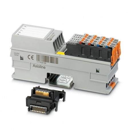
AXL F AO4 XC 1H 2702153 PHOENIX CONTACT I/O module
$0.00USD
3182 in stock
Key Specifications
:Transient protection; Suppressor diode
Type:block modular
Depth:54 mm
Width:35 mm
Supplier Information
Products: 0
Usually ships within 2-3 business days
Quality Guaranteed
Fast Shipping
Technical Support
Technical Specifications
| Parameter | Value |
|---|---|
| Transient protection; Suppressor diode | |
| Type | block modular |
| Depth | 54 mm |
| Width | 35 mm |
| Height | 126.1 mm |
| Certificate | UL 20 ATEX 2441X |
| Output name | Analog outputs |
| Current draw | max. 150 mA |
| Data formats | IB IL, S7-compatible |
| Product type | I/O component |
| Mounting type | DIN rail mounting |
| Identification | II 3 G Ex ec IIC T4 Gc |
| Product family | Axioline F |
| Supply voltage | 5 V DC (via bus base module) |
| Connection name | Axioline F connector |
| Article revision | 07 |
| Pollution degree | 2 (IEC 60664-1, EN 60664-1) |
| Protection class | III (IEC 61140, EN 61140, VDE 0140-1) |
| Stripping length | 8 mm |
| Connection method | Bus base module |
| Mounting position | any (no temperature derating) |
| Number of outputs | 4 |
| Scope of delivery | including bus base module and Axioline F connectors |
| Input address area | 8 Byte |
| Note on dimensions | The depth applies when a TH 35-7.5 DIN rail is used (in accordance with EN 60715). |
| Protective circuit | Short-circuit and overload protection; electronic |
| Special properties | Extreme conditions version |
| Transmission speed | 100 Mbps |
| Dimensional drawing | |
| Note on application | Only for industrial use |
| Output address area | 8 Byte |
| Process data update | 140 µs |
| Degree of protection | IP20 |
| Number of interfaces | 2 |
| Overvoltage category | II (IEC 60664-1, EN 60664-1) |
| Supply voltage range | 19.2 V DC ... 30 V DC (including all tolerances, including ripple) |
| Connection technology | 2-conductor |
| Current output signal | 0 mA ... 20 mA |
| Voltage output signal | 0 V ... 5 V |
| References to standards | EN IEC 60079-0, EN IEC 60079-7 |
| Required parameter data | 14 Byte |
| Air pressure (operation) | 70 kPa ... 106 kPa (up to 3000 m above sea level) |
| D/A converter resolution | 16 bit |
| Conductor cross section AWG | 24 ... 16 |
| Required configuration data | 7 Byte |
| Conductor cross section rigid | 0.2 mm² ... 1.5 mm² |
| Note on the connection method | Please observe the information provided on conductor cross sections in the “Axioline F: system and installation” user manual. |
| Conductor cross section, rigid | 0.2 mm² ... 1.5 mm² |
| Ambient temperature (operation) | -25 °C ... 60 °C (Standard, applications with UL approval, use in zone 2 potentially explosive area) |
| Load/output load current output | ≤ 500 Ω |
| Load/output load voltage output | ≥ 1 kΩ |
| Representation of output values | 16 bits (15 bits + sign) |
| Air pressure (storage/transport) | 70 kPa ... 106 kPa (up to 3000 m above sea level) |
| Conductor cross section flexible | 0.2 mm² ... 1.5 mm² |
| Permissible humidity (operation) | 5 % ... 95 % (non-condensing) |
| Conductor cross section, flexible | 0.2 mm² ... 1.5 mm² |
| Ambient temperature (storage/transport) | -40 °C ... 85 °C |
| Note regarding the connection technology | shielded, twisted pair |
| Permissible humidity (storage/transport) | 5 % ... 95 % (non-condensing) |
| Test voltage: 24 V supply (I/O)/analog outputs | 500 V AC, 50 Hz, 1 min. |
| Test voltage: Analog outputs/functional ground | 500 V AC, 50 Hz, 1 min. |
| Maximum power dissipation for nominal condition | 3.4 W |
| Test voltage: 24 V supply (I/O) / functional ground | 500 V AC, 50 Hz, 1 min. |
| Test voltage: 5 V supply of the local bus (UBus)/analog outputs | 500 V AC, 50 Hz, 1 min. |
| Test voltage: 5 V supply of the local bus (UBus) / functional ground | 500 V AC, 50 Hz, 1 min. |
| Test voltage: 5 V supply of the local bus (UBus) / 24 V supply (I/Os) | 500 V AC, 50 Hz, 1 min. |
Product Description
AxiolineF, Analog Output Module, Analog Outputs: 4, 0 V ... 5 V, -5 V ... 5 V, 0 V ... 10 V, -10 V ... 10 V, 0 mA... 20 mA, 4 mA... 20 mA, connection technology: 2 conductors, transmission rate on loc
Key Features
- Industrial grade quality
- RoHS compliant
- CE certified
- 1-year warranty
Product Documents
Datasheet
Technical specifications and performance data
User Manual
Installation and operation guide


