In Stock Hot Product
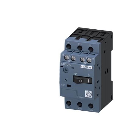
3RV1011-1EA15-0BA0
3RV1011-1EA15-0BA0 SIEMENS SPECIAL TYPE CIRCUIT BREAKER SIZE S00, FOR MOTOR PROTECTION, CLASS 10 A-RELEASE ..
$0.00USD
3766 in stock
Key Specifications
Depth:81 mm
Width:45 mm
Height:90 mm
— solid:2x (0.5 ... 1.5 mm²), 2x (0.75 ... 2.5 mm²)
Supplier Information
SIEMENS
Products: 367174
Usually ships within 2-3 business days
Quality Guaranteed
Fast Shipping
Technical Support
Technical Specifications
| Parameter | Value |
|---|---|
| Depth | 81 mm |
| Width | 45 mm |
| Height | 90 mm |
| — solid | 2x (0.5 ... 1.5 mm²), 2x (0.75 ... 2.5 mm²) |
| Trip class | CLASS 10 |
| ● at 24 V | 2 A |
| ● at 60 V | 0.15 A |
| ● at AC-3 | |
| — stranded | 2x (0.5 ... 1.5 mm²), 2x (0.75 ... 2.5 mm²) |
| ● at 230 V | 0.5 A |
| Mounting type | screw and snap-on mounting onto 35 mm standard mounting rail according to DIN EN 50022 |
| — Backwards | 0 mm |
| Operating power | |
| — at the side | 0 mm |
| ● rated value | 690 V |
| Product function | |
| Required spacing | |
| Shock resistance | 25g / 11 ms |
| ● on the front | IP20 |
| Mounting position | any |
| Operating current | |
| Operating voltage | |
| Product extension | |
| product brand name | SIRIUS |
| ● during storage | -50 ... +80 °C |
| Ambient temperature | |
| Operating frequency | |
| Product designation | circuit breaker |
| Protection class IP | |
| ● at AC-3 maximum | 15 1/h |
| ● Auxiliary switch | Yes |
| ● during operation | -50 ... +60 °C |
| ● during transport | -50 ... +80 °C |
| Design of the product | for motor protection |
| Number of CO contacts | |
| ● for main contacts | |
| — at 400 V rated value | 4 A |
| ● for auxiliary contacts | 0 |
| Power loss [W] total typical | 6 W |
| ● for main current circuit | screw-type terminals |
| Type of electrical connection | |
| Design of the auxiliary switch | transverse |
| ● at AC at 240 V rated value | 100 kA |
| ● at AC at 400 V rated value | 100 kA |
| ● at AC at 500 V rated value | 3 kA |
| ● at AC at 690 V rated value | 2 kA |
| ● with side-by-side mounting | |
| ● at AC-3 rated value maximum | 690 V |
| ● of the main contacts typical | 500 |
| Surge voltage resistance rated value | 6 000 V |
| ● at AWG conductors for main contacts | 2x (18 ... 14) |
| Mechanical service life (switching cycles) | |
| Type of connectable conductor cross-sections | |
| — finely stranded with core end processing | 2x (0.5 ... 1.5 mm²), 2x (0.75 ... 2.5 mm²) |
| ● at AWG conductors for auxiliary contacts | 2x (18 ... 14) |
| ● for auxiliary and control current circuit | screw-type terminals |
| Operating current of auxiliary contacts at AC-15 | |
| Operating current of auxiliary contacts at DC-13 | |
| Maximum short-circuit current breaking capacity (Icu) | |
| Installation altitude at height above sea level maximum | 2 000 m |
| ● removable terminal for auxiliary and control circuit | No |
| Design of the overcurrent release and short-circuit release | thermomagnetic |
| Arrangement of electrical connectors for main current circuit | front side |
| Adjustable pick-up value current of the current-dependent overload release | 2.8 ... 4 A |
Product Description
More details
Key Features
- Industrial grade quality
- RoHS compliant
- CE certified
- 1-year warranty
Product Documents
Datasheet
Technical specifications and performance data
User Manual
Installation and operation guide


